您现在的位置是:首页 > 家电

选择数字和字母显示配置的MAX6954和MAX6955的SP

2020-03-18 00:01:28

Abstract: This applicaTIon note uses a web based Java program to allow an engineer to simulate the wide range of display configuraTIons of the MAX6954 and MAX6955 serial interfaced LED display drivers. The tool enables the user to check which LED digit, character, discrete and combinaTIons may be used.

This applicaTIon note discusses connecting the MAX6954 and MAX6955 to a variety of LED display types. The MAX6954 and MAX6955 are 7-, 14- and 16-Segment LED display drivers that are controlled through a high-speed SPI (MAX6954) or I²C (MAX6955) serial interface.

Determining the Appropriate Connection Scheme for your Design

To aid in designing a MAX6954/MAX6955 controlled Display an online tool is available. This tool allows you to enter the display digit types you intend to use, and provides the corresponding connection scheme, as well as the Digit Type Register contents for the design. The MAX6954/MAX6955 Connection Scheme Tool requires a web browser that supports JavaScript. If you experience any problems with the tool, please contact Maxim Customer Applications and an engineer will be happy to help.

Electrical Connection of the MAX6954 or MAX6955 to LED Displays

Each MAX6954 or MAX6955 drives common-cathode mono-color digits (Table 1), or bi-color digits (Table 2). The multiplexing engine doesn't know or care whether mono-color or bi-color displays are used; bi-color digits are treated both electrically and in software as two mono-color digits.

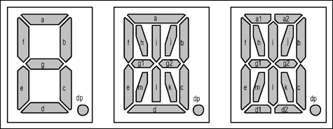
Figure 1. Segment labeling for 7-, 14-, and 16-segment displays.

Table 1. MAX6954 and MAX6955 Connection to 8 Monocolor 16-Segment Digits Digit O0 O1 O2 O3 O4 O5 O6 O7 O8 O8 O10 O11 O12 O13 O14 O15 O16 O17 O18 0 CC0   a1 a2 b c d1 d2 e f g1 g2 h i j k l m dp 1   CC1 a1 a2 b c d1 d2 e f g1 g2 h i j k l m dp 2 a1 a2 CC2   b c d1 d2 e f g1 g2 h i j k l m dp 3 a1 a2   CC3 b c d1 d2 e f g1 g2 h i j k l m dp 4 a1 a2 b c CC4   d1 d2 e f g1 g2 h i j k l m dp 5 a1 a2 b c   CC5 d1 d2 e f g1 g2 h i j k l m dp 6 a1 a2 b c d1 d2 CC6   e f g1 g2 h i j k l m dp 7 a1 a2 b c d1 d2   CC7 e f g1 g2 h i j k l m dp

Table 2. MAX6954 and MAX6955 Connection to 4 Bicolor 16-Segment Digits Digit O0 O1 O2 O3 O4 O5 O6 O7 O8 O8 O10 O11 O12 O13 O14 O15 O16 O17 O18 0 CC0   a1 a2 b c d1 d2 e f g1 g2 h i j k l m dp 1   CC1 a1 a2 b c d1 d2 e f g1 g2 h i j k l m dp 2 a1 a2 CC2   b c d1 d2 e f g1 g2 h i j k l m dp 3 a1 a2   CC3 b c d1 d2 e f g1 g2 h i j k l m dp 4 a1 a2 b c CC4   d1 d2 e f g1 g2 h i j k l m dp 5 a1 a2 b c   CC5 d1 d2 e f g1 g2 h i j k l m dp 6 a1 a2 b c d1 d2 CC6   e f g1 g2 h i j k l m dp 7 a1 a2 b c d1 d2   CC7 e f g1 g2 h i j k l m dp

Driving Multiple Digit Types using the MAX6954 or MAX6955

The Digit Type (0x0C) and Decode Mode (0x01) Registers can be used to configure the MAX6954/MAX6955 to drive multiple display types simultaneously. Using the connection scheme in Tables 3 and 4 the MAX6954/MAX6955 drive (1) 16-Segment Monocolor Digit, (1) 14-Segment Monocolor Digit, (1) 7-Segment Bicolor Digit, (3) 7-Segment Monocolor Digits, (1) 14-Segment Bicolor Digit, (8) Bicolor Discrete LEDs and (8) Monocolor Discrete LEDs. The corresponding Digit Type and Decode Mode Register values are contained in Tables 5 and 6.

Table 3. MAX6954 and MAX6955 Slot Assignments Register Data SLOT 4 SLOT 3 SLOT 2 SLOT 1 D7 D6 D5 D4 D3 D2 D1 D0 (8) Disc. Bi. LEDs (Green 1/2) 7-Seg. Mono. (8) Disc. Bi. LEDs (Red 1/2) 7-Seg. Mono. 14-Seg. Bi. (Green 1/2) 14-Seg. Bi. (Red 1/2) 16-Seg. Mono. 14-Seg. Mono. 7-Seg. Mono. 7-Seg. Bi. (Green 1/2) (8) Disc. Mono. LEDs 7-Seg. Bi. (Red 1/2).

Table 4. Example MAX6954 and MAX6955 Connection Scheme Digit O0 O1 O2 O3 O4 O5 O6 O7 O8 O8 O10 O11 O12 O13 O14 O15 O16 O17 O18 0 CC0   1a   1b 1c 1d 1dp 1e 1f 1g 2a 2b 2c 2d 3e 2f 2g 2dp 1   CC1 1a   1b 1c 1d 1dp 1e 1f 1g 2a 2b 2c 2d 3e 2f 2g 2dp 2 a   CC2   b c d   e f g1 g2 h i j k l m dp 3 a1 a2   CC3 b c d1 d2 e f g1 g2 h i j k l m dp 4 a   b c CC4   d   e f g1 g2 h i j k l m dp 5 a   b c   CC5 d   e f g1 g2 h i j k l m dp 6 1a   1b 1c 1d 1dp CC6   1e 1f 1g 2a 2b 2c 2d 2e 2f 2g 2dp 7 1a   1b 1c 1d 1dp   CC7 1e 1f 1g 2a 2b 2c 2d 2e 2f 2g 2dp

Table 5. Example MAX6954 and MAX6955 Digit Type Register Contents (0x0C) Register Data D7 D6 D5 D4 D3 D2 D1 D0 0 0 1 1 0 1 0 0

Table 6. Example MAX6954 and MAX6955 Decode Mode Register Contents (0x01) Register Data D7 D6 D5 D4 D3 D2 D1 D0 0 0 1 1 1 1 0 0