The MAX6950 and MAX6951 are five-digit and eight-digit common-cathode LED display drivers controlled through a high-speed SPI serial interface. This applicaTIon note describes a uTIlity program that allows a MAX6950 or MAX6951 driver to be controlled from a PC. The utility can be used stand-alone simply to help an engineer become familiar with the registers and functions of the drivers. Moreover, it can be used to "prove" a display board prototype by directly controlling the MAX6950 or MAX6951 registers before the equipment's software is designed.
Requirements
The requirements are a PC running Windows 95, 98, 98SE, ME, NT, or 2000, with a parallel printer port configured for either LPT1 or LPT2.Description
The utility is a Visual BASIC 5 program called MAX6950.EXE that requires the standard Visual BASIC run-time library MSVBVM50.DLL in order to run at all. The program uses the DriverLINX™ freeware parallel port driver DLPortIO.DLL that provides the Win32 DLL hardware I/O functions not available as standard in Visual BASIC. Windows NT and 2000 users also require the DLPortIO.SYS kernel mode driver. Both of these drivers are copyright Scientific Software Tools, Inc. (www.driverlinx.com). DriverLINX is a registered trademark of Scientific Software Tools, Inc.Installation
To install to a Windows 95, 98, 98SE, or ME platform, download the MAX6950-95.EXE file. This is a WinZIP self-extracting archive that contains ReadMe.txt, ReadMeSST.txt, MAX6950.EXE, DLPortIO.DLL, and MSVBVM50.DLL. The default download directory is C:\MAX6950. MSVBVM50.DLL can be deleted if the library is already registered on the computer.To install to a Windows NT or 2000 platform, download the MAX6950-NT.EXE file. This is a WinZIP self-extracting archive that contains ReadMe.txt, ReadMeSST.txt, MAX6950.EXE, PORT95NT.EXE, and MSVBVM50.DLL. The default download directory is C:\MAX6950. PORT95NT.EXE is the install program for the DriverLINX drivers that installs and registers the DLPortIO.DLL library and DLPortIO.SYS driver. PORT95NT.EXE can be deleted after installation. Windows 95, 98, 98SE, or ME users can also use this installation procedure.
Source Code
The source code for this application note is available http://www.maxim-ic.com/products/display/software/.Connecting a MAX6950 or MAX6951 to the Parallel Port
This utility uses three of the eight parallel port printer output lines to simulate SPI serial interface activity. You can select either the LPT1 or LPT2 port from the software. The port can be a standard ECP or EPP type. The connections are shown in Figure 2.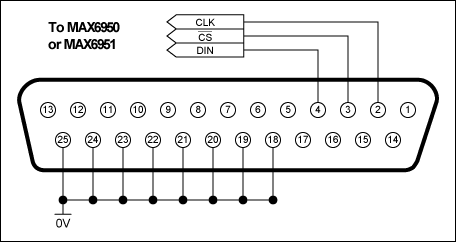
Figure 1. MAX6950 or MAX6951 connections to the parallel port.
The MAX6950 or MAX6951 SPI port pins can be connected directly as shown above only if the connection is short (certainly less than 1m) and the MAX6950 or MAX6951 is running from a +5V supply. The reason for the short connection requirement is that the MAX6950 and MAX6951 have a very fast (26Mbits-1) responding serial interface that is sensitive to spikes and glitches picked up over a long cable. The PC outputs are nominally TTL level, but they can be 5V CMOS level, depending on the exact implementation. The MAX6950 and MAX6951 inputs must not exceed the supply voltage, so a direct connection mandates the MAX6950 or MAX6951 running from a +5V supply. The MAX6950 and MAX6951 inputs switch at fairly low logic thresholds (0.4V maximum, 2.4V minimum), making them compatible with TTL independent of their supply voltage.
It is recommended that the three SPI signals are each connected through a termination network, as shown in Figure 2. The termination performs the following functions:
- R1 limits the "fault" current flow when the PC signal is high at 5V and the MAX6950 or MAX6951 is running from a lower supply. The current is steered by the MAX6950 or MAX6951's input protection diodes into the supply. The worst-case current is less than 5mA, which can be driven safely into the MAX6950 or MAX6951 this way.
- R2 provides a pull-up to the MAX6950 or MAX6951's supply rail, assisting the weak TTL logic high drive over a longer cable. It also keeps the SPI CS-bar input de-asserted.
- C1 provides a small glitch filter by making a one-pole filter with R1 and R2 with a time constant of about 100ns. The program runs the SPI interface somewhere between 100kbits-1 and 1Mbits-1 (depending on the PC), so the filter does not affect the interface speed.
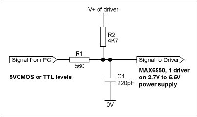
Figure 2. Recommended SPI interface termination network.
The interface connection to the parallel port can be tested with the "Test Stream" facility that can be found under Configuration Instructions when the program is running. The "Test Stream" facility transmits the no-op instruction continuously to the MAX6950 or MAX6951 (if connected), allowing the interface connections to be verified.
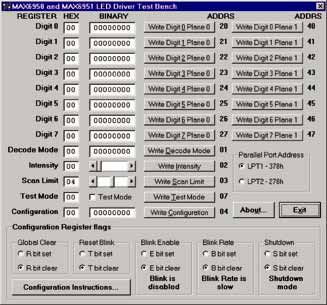
Figure 3. Program display on startup.