免费注册参加在线研讨会,学习如何分析、测量并最终解决音频系统的设计问题 (English only) 。
What is the effect of source impedance versus sound pressure when driving an audible PZT?
This has a direct effect on the peak capacity of a power supply that is used for driving the PZT.Is there any detectable sound pressure difference when driving an audible PZT single-ended versus bipolar, with the same peak to peak amplitude?
This can impact drive circuit complexity.What does the impedance of a PZT look like?
This can affect peak power supply capacity as well as filtering requirements.Three common PZTs manufactured by Mallory (North American Capacitor Company) were chosen for investigation of driving source impedance versus sound pressure, single and bipolar drive versus sound pressure, and PZT impedance characteristics.
Structure of PZTs
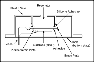
Figure 1 illustrates a cut-away view of a typical audible PZT. A piezoceramic plate is plated with silver on both sides. One side is bonded to a thin brass plate around the piezoceramic plate's circumference using an adhesive. This side becomes one electrode connection. The other side of the piezoceramic plate becomes the second electrode contact. The brass plate is attached to a supporting ring, which is part of the molded plastic case, using a silicone adhesive.
Figure 1. Cut-away view of audible PZT.
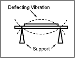
There are two possible ways to excite the audible PZT to produce sound; by driving it with a single-ended signal (i.e., 0V to +5V) or with a bipolar signal (i.e., -2.5V to +2.5V). Figure 2 illustrates the mechanical deflection about a midpoint of mechanical zero when an audible PZT is driven with a bipolar signal.

Figure 2. Bipolar deflection.
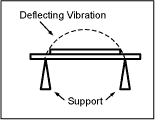
Figure 3 shows the mechanical deflection when a single-ended signal is used to drive the PZT. When a single-ended signal is applied, the PZT deflects one direction from the mechanical zero point. This unipolar deflection will be larger in amplitude from zero than when the bipolar signal was applied as in Figure 2. The resultant total deflection will be the same for a bipolar signal of -2.5V to +2.5V as a single-ended signal of 0V to +5V.

Figure 3. Single-ended deflection.
Equipment and Test Setup
Equipment:
Tektronix TDS3012 2-Channel Color Digital Phosphor Oscilloscope (100MHz, 1.25GS/s)HP 33120 15MHz Function / Arbitrary Waveform Generator
Tektronix AM503 Current Probe Amplifier
Tektronix A6302 Current Probe
Radio Shack Analog-Display Sound-Level Meter, Cat. #33-2050 (see Figure 4)

Figure 4. Radio Shack analog-display sound-level meter.
Test Setup:
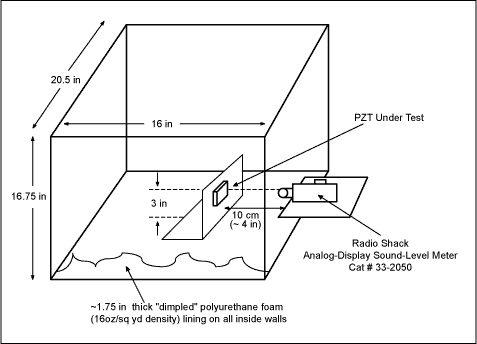
The test setup for testing sound pressure is shown in Figure 5. A box made of processed organic composite with sound-deadening qualities was lined with "dimpled" polyurethane foam to create a psuedo-anechoic chamber. The Radio Shack sound-level meter was placed outside of the chamber with the meter's microphone inserted into the chamber through a hole in the back of the chamber. An L-shaped cardboard stand was constructed, in which the PZT under test could be attached. This allowed for precise positioning of the PZT from the meter's microphone.
Figure 5. Sound pressure test setup.