ST公司的SPC584Cx和SPC58ECx系列产品是用于汽车电子的32位Power Architecture MCU,采用两个处理器核e200z420和一个处理器和e200z0,工作频率高达180MHz,满足规范AEC-Q100,具有可变长度编码(VLE),集成了4224 KB (4096 KB代码闪存+128 KB 数据闪存)闪存,以及384 KB通用SRAM,主要用在汽车电子.本文介绍了SPC584Cx和SPC58ECx主要特性,以及评估板AEKD-USBTYPEC1(AEK-USB-2TYPEC1和SPC58EC-DISP)主要特性,框图,电路图和材料清单.
The SPC584Cx and SPC58ECx microcontroller are the first in a new family of devices superseding the SPC564Cx and SPC56ECx family. SPC584Cx and SPC58ECx build on the legacy of the SPC564Cx and SPC56ECx, while introducing new features coupled with higher throughput to provide substantial reduction of cost per feature and significant power and performance improvement (MIPS per mW). On the SPC584Cx and SPC58ECx devices, there are two processor cores e200z420 and one e200z0 core embedded in the Hardware Security Module.
SPC584Cx和SPC58ECx主要特性:
AEC-Q100 qualified ?
High performance e200z420n3 dual core:
– 32-bit Power Architecture technology CPU
– Core frequency as high as 180 MHz
– Variable Length Encoding (VLE) ?
4224 KB (4096 KB code flash + 128 KB data flash) on-chip flash memory: supports read during program and erases operations, and multiple blocks allowing EEPROM emulation 176 KB HSM dedicated flash memory (144 KB code + 32 KB data) ?
384 KB on-chip general-purpose SRAM (in addition to 128 KB core local data RAM: 64 KB included in each CPU) ?
?Multi-channel direct memory access controller (eDMA) with 64 channels ?
1 interrupt controller (INTC)
?Comprehensive new generation ASIL-B safety concept:
– ASIL-B of ISO 26262
– FCCU for collection and reaction to failure notifications
– Memory Error Management Unit (MEMU) for collection and reporting of error events in memories
– Cyclic redundancy check (CRC) unit ?
?Crossbar switch architecture for concurrent access to peripherals, Flash, or RAM from multiple bus masters with end-to-end ECC ?
Body cross triggering unit (BCTU):
– Triggers ADC conversions from any eMIOS channel
– Triggers ADC conversions from up to 2 dedicated PIT_RTIs
Enhanced modular IO subsystem (eMIOS): up to 64 timed I/O channels with 16-bit counter resolution Enhanced analog-to-digital converter system with:
– 3 independent fast 12-bit SAR analog converters
– 1 supervisor 12-bit SAR analog converter
– 1 10-bit SAR analog converter with STDBY mode support: ?
Communication interfaces:
– 18 LINFlexD modules
– 8 deserial serial peripheral interface (DSPI) modules
– 8 MCAN interfaces with advanced shared memory scheme and ISO CAN-FD support
– Dual channel FlexRay controller
– 1 Ethernet controller 10/100 Mbps, compliant IEEE 802.3-2008
? Low power capabilities:
– Versatile low power modes
– Ultra low power standby with RTC
– Smart wake-up Unit for contact monitoring
– Fast wakeup schemes ?
Dual phase-locked loops with stable clock domain for peripherals and FM modulation domain for computational shell ?
Nexus development interface (NDI) per IEEE-ISTO 5001-2003 standard, with some support for 2010 standard ?
Boot assist Flash (BAF) supports factory programming using a serial bootload through the asynchronous CAN or LIN/UART ?
Junction temperature range: -40℃ to 150℃
评估板AEKD-USBTYPEC1
USB Type-C? and USB Power Delivery evaluation kit based on the automotive grade SPC58 MCU and AutoDevKit development initiative
The AEKD-USBTYPEC1 evaluation kit is designed to let you test the USB PowerDelivery protocol stack implemented on the ASIL-B automotive grade 32-bit PowerArchitecture? microcontroller SPC58 C (Chorus) line (from 1 to 10 MB flash, single ormulti-core, including ISO CAN FD and Ethernet peripherals).
The USB Type-C and USB Power Delivery specifications allow smarter connectivity with fewer cables, lessconnectors and universal chargers. The Type-C connector supports all the features of previous standards, andports can be configured to only supply power in a Provider role, only sink power in a Consumer role, or be able to switch between both in a Dual role.
Both data and power roles can be independently and dynamically swapped using the USB Power Deliveryprotocol.
Most automotive applications require support for the Provider role only. When a USB device is connected, theProvider and the device (Consumer) negotiate a contract for the power objects through configuration channels.
The message exchange between Provider and Consumer are listed below:
1. The Provider sends a Source Capabilities message to the Consumer, advertising its powercapabilities.
2. The device then sends a Request for one of the advertised power profiles.
3. The provider accepts or rejects this request according to its power balance
4. If confirmed, provider sends as an Accept message to the device
5. The provider then switches to the requested power profile and sends a PS_Readyconfirmation message
Each received message is acknowledged with a GoodCRCto confirm correct reception. Incorrect receptions areignored and persistent communication errors should trigger a soft reset to re-establish communication. If the errorpersists,a hard reset is performed.
评估板AEKD-USBTYPEC1主要特性:
? Kit consisting of two boards:
– Dual-port USB Type-C function board (AEK-USB-2TYPEC1)
– SPC58 Chorus discovery board (SPC58EC-DISP)
? USB Power Delivery software stack pre-loaded on SPC58 discovery board
? Power board connector on USB function board
? Power Data Objects (PDO)
– 5 V 500 mA available without external power board
– other PDOs possible if a compatible power board (not included) isconnected
? Downloadable (STSW-USB2TYPEC1) compiled flash image firmware
? Portion of connector on SPC58 Chorus discovery board available for extensionsas part of the AutoDevKit development initiative
? All key ST components are qualified automotive grade
? RoHS compliant
图1.评估板AEKD-USBTYPEC1外形图
图2.评估板AEKD-USBTYPEC1框图
评估板AEKD-USBTYPEC1包括:
The AEKD-USBTYPEC1 kit includes the following components:
? SPC58EC-DISP discovery board
? AEK-USB-2TYPEC1 USB function board
? STSW-USB2TYPEC1 firmware
? USB Type-C to USB Type-C cable (not electrically marked)
? 12V 2A AC/DC power supply to power the SPC58EC-DISP board
? Type-A to Mini USB cable for Test mode screen output to the PC and board programming
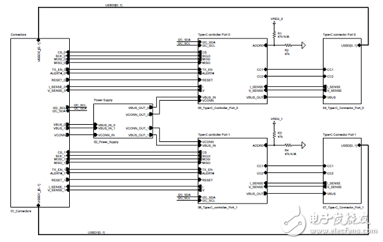
图3.评估板AEK-USB-2TYPEC1电路图(1):框图
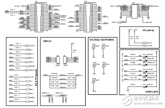
图4.评估板AEK-USB-2TYPEC1电路图(2):连接器
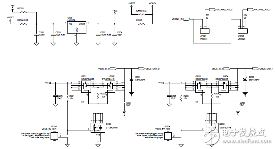
图5.评估板AEK-USB-2TYPEC1电路图(3):电源
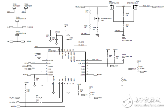
图6.评估板AEK-USB-2TYPEC1电路图(4):Type C控制端口0
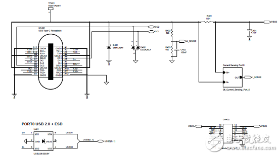
图7.评估板AEK-USB-2TYPEC1电路图(5):Type C连接器端口0
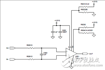
图8.评估板AEK-USB-2TYPEC1电路图(6):电流传感器端口0
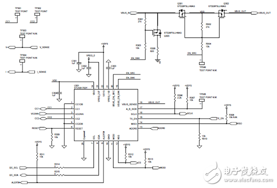
图9.评估板AEK-USB-2TYPEC1电路图(7):Type C控制端口1
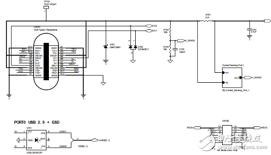
图10.评估板AEKD-USB -2TYPEC1电路图(8):Type C连接器端口1
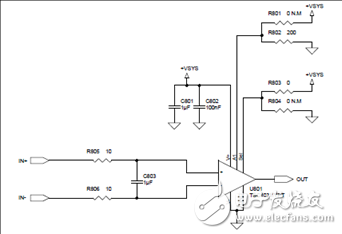
图11.评估板AEKD-USB -2TYPEC1电路图(9):电流传感器端口1
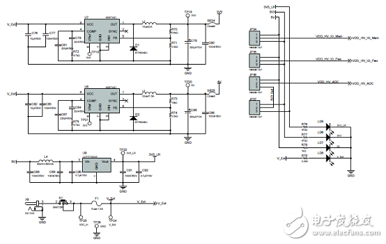
图12.评估板SPC58EC-DISP板电路图(1):电源
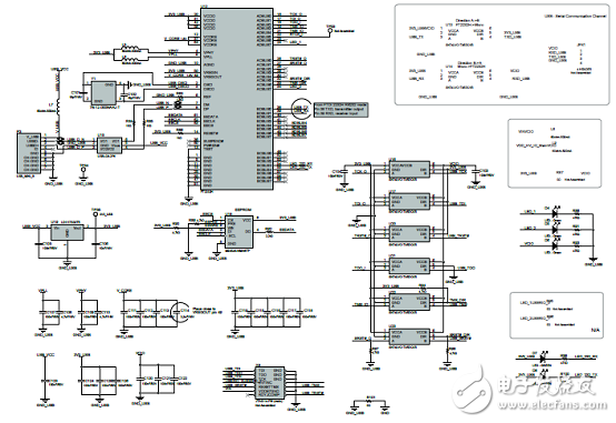
图13.评估板SPC58EC-DISP板电路图(2):USB和调试
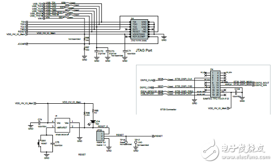
图14.评估板SPC58EC-DISP板电路图(3):JTAG端口,重置开关和ST33连接器
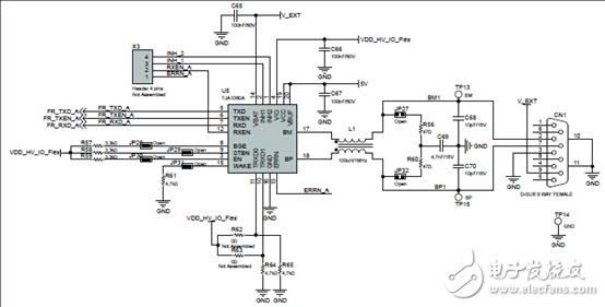
图15.评估板SPC58EC-DISP板电路图(4):FlexRay
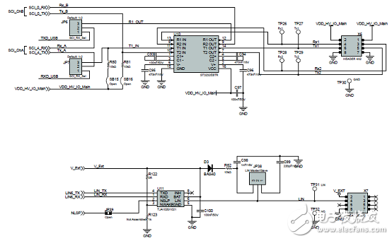
图16.评估板SPC58EC-DISP板电路图(5):RS232和LIN
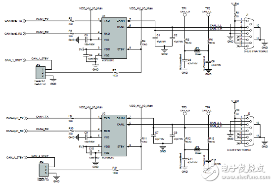
图17.评估板SPC58EC-DISP板电路图(6):CAN
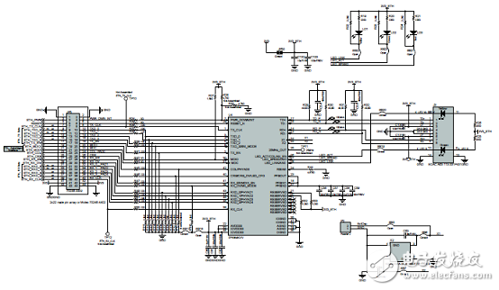
图18.评估板SPC58EC-DISP板电路图(7):以太网
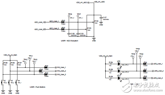
图19.评估板SPC58EC-DISP板电路图(8):用户接口元件
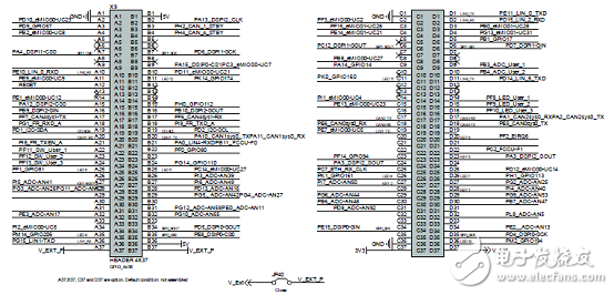
图20.评估板SPC58EC-DISP板电路图(9):扩展连接器
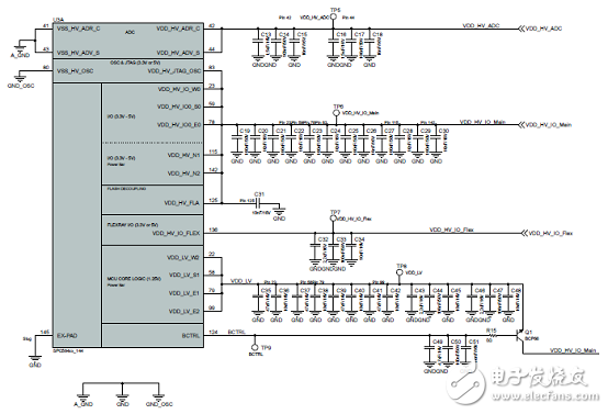
图21.评估板SPC58EC-DISP板电路图(10):MCU电源管理
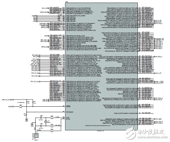
图22.评估板SPC58EC-DISP板电路图(11):MCU IO信号
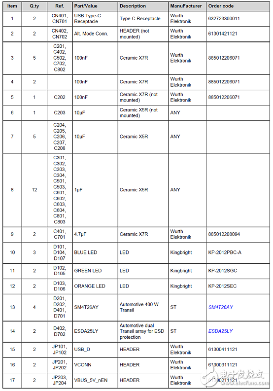
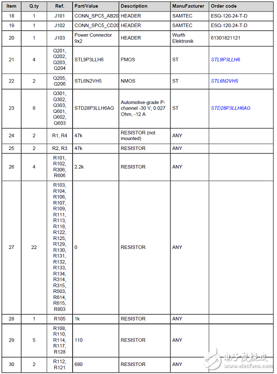
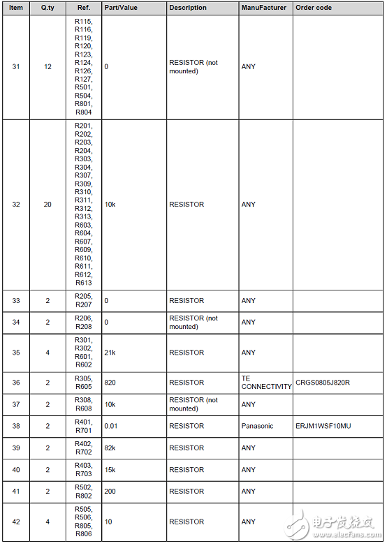
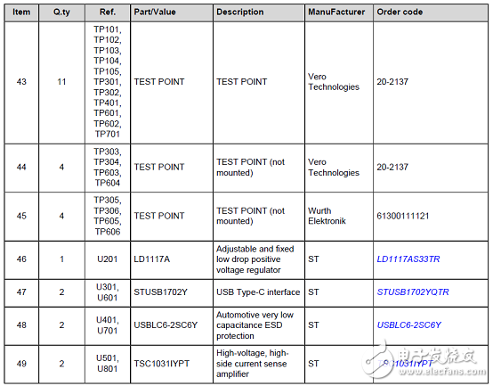
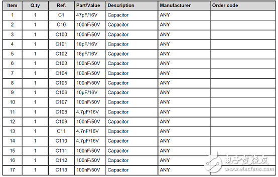
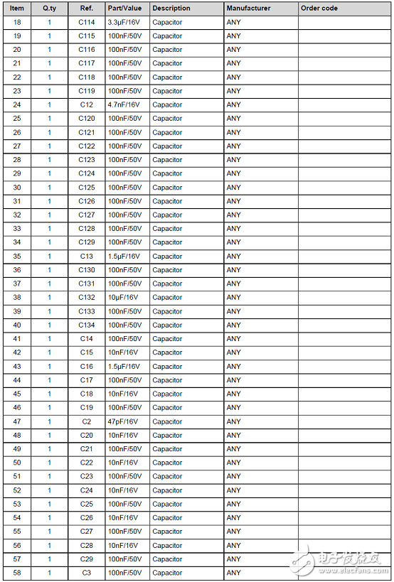
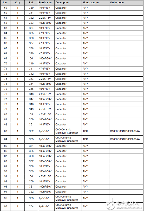
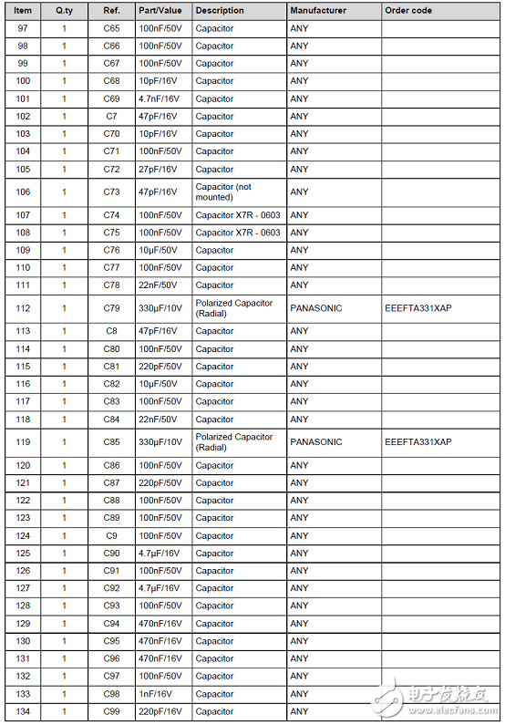
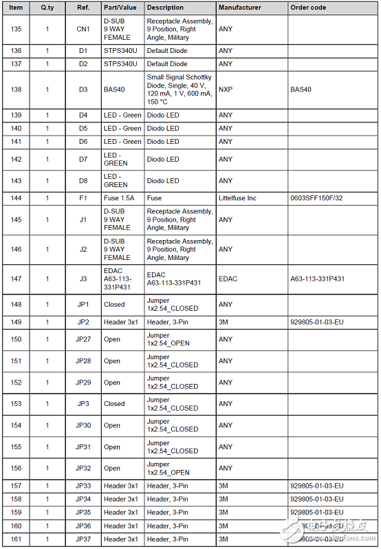
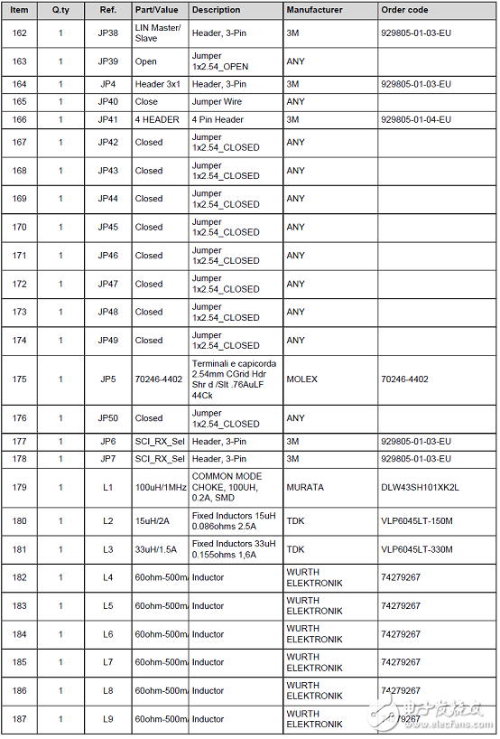
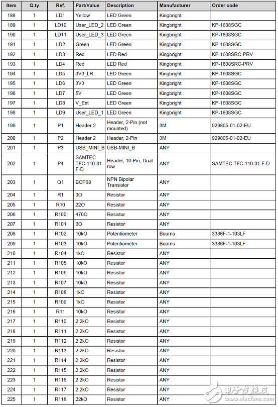
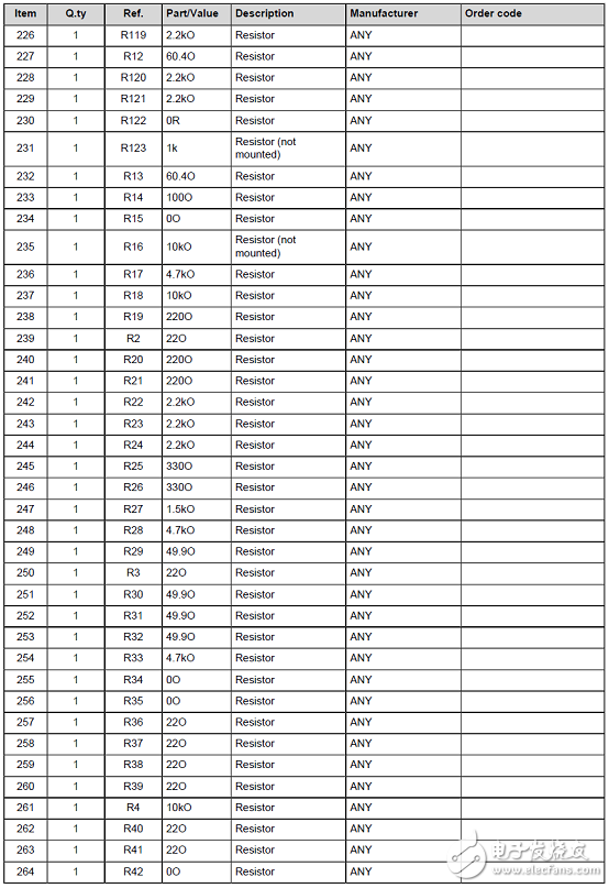
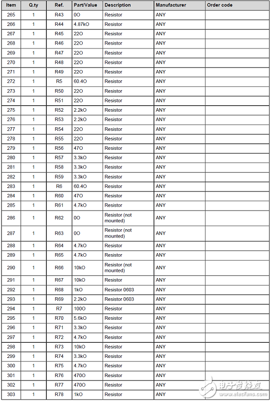
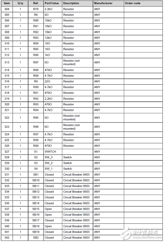
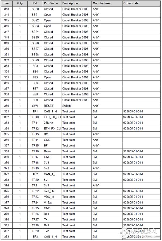
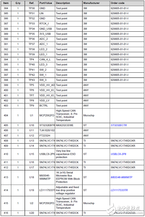
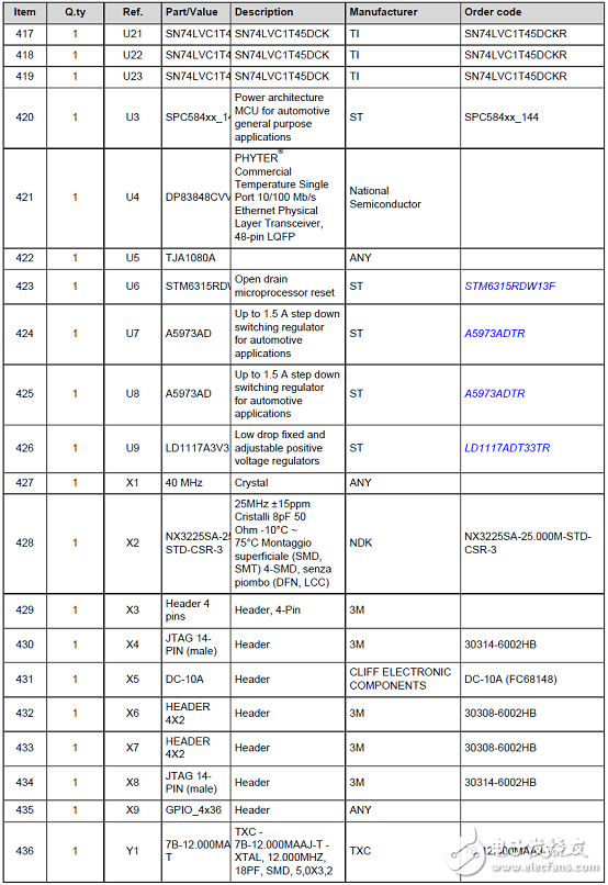
AEK-USB-2TYPEC1板材料清单:
SPC58EC-DISP板材料清单:
详情请见:
https://www.st.com/content/ccc/resource/technical/document/user_manual/group1
/16/5c/9d/85/99/d9/48/4f/DM00528550/files/DM00528550.pdf/jcr:content/translations/en.DM00528550.pdf
和https://www.st.com/content/ccc/resource/technical/layouts_and_diagrams/schematic_pack
/group0/30/f6/ae/90/a8/d0/4e/0d/AEKD-USBTYPEC1_SCHEMATIC/files/aekd-usbtypec1_schematics.pdf/jcr:content/translations/en.aekd-usbtypec1_schematics.pdf
以及https://www.st.com/content/ccc/resource/technical/document/bill_of_materials/group0
/75/8e/27/d5/bb/f0/4e/17/AEKD-USBTYPEC1_BOM/files/aekd-usbtypec1_bom.pdf/jcr:content/translations/en.aekd-usbtypec1_bom.pdf
en.DM00528550.pdf
aekd-usbtypec1.pdf
en.aekd-usbtypec1_bom.pdf
en.aekd-usbtypec1_schematics.pdf