引言
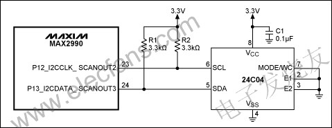
本文介绍了如何通过MAX2990电力线通信调制解调器的I2C接口与外部EEPROM 24C04连接,并给出了相应的固件例程。I²C总线受控于MAX2990 (主机),24C04 EEPROM为从机器件。以下框图给出了本文示例的硬件配置。
固件说明
I²C接口初始化
一旦使能I²C模块,SCL和SDA必须配置成漏极开路状态,以确保I²C总线通信正常。由于I²C是GPIO端口的一个替代功能,固件必须确保SCL和SDA输入在初始化期间禁止上拉(通过对端口控制器的输出位写零实现)。
示例中,时钟频率为250kHz。首先需要配置MAX2990的I²C接口:
PO1_bit.Bit2 = 0; 		// Disables the GPIO funcTIon of the
PO1_bit.Bit3 = 0; 		// I2C pins

I2CCN_bit.I2CEN = 0; 	// Makes sure that I2C is disabled
			// to allow the changing of the I2C setTIngs

I2CCN_bit.I2CMST = 1; 		// Sets the I2C engine to master mode
I2CCN_bit.I2CEA = 0; 		// 7-bit address mode
I2CCK_bit.I2CCKL = 0x40; 	// 2µs CLK-low, to define I2C frequency
I2CCK_bit.I2CCKH = 0x40; 	// 2µs CLK-high, to define I2C frequency

I2CTO = 200; 		// I2C_TIMEOUT
I2CST = 0x400; 		// Resets I2C status register

I2CCN_bit.I2CEN = 1; 		// Enables the I2C engine
写模式
写入24C04 EEPROM时,必须通过I²C接口写入以下字节:
- EEPROM的I²C总线地址(这里为0xA0)
- EEPROM存储器的地址
- 数据字节(地址将自动递增)
示例中试图写入以下字节,从0x00地址开始,向EEPROM写入:0x12、0x34、0x56、0x78和0x90。
i2c_init_write(); 	// Sets the MAX2990 I2C Engine into write mode
i2c_write(0x50); 	// 24C04 write (adr = 0b1010 000 0) = 0xA0
		// The MAX2990 I2C engine shifts the I2C address by
			// 1 bit, because it will generate the R/W bit
			// automaTIcally

i2c_write(0x00); 	// word address location
i2c_write(0x12); 	// data1
i2c_write(0x34); 	// data2
i2c_write(0x56); 	// data3
i2c_write(0x78); 	// data4
i2c_write(0x90); 	// data5
I2C_STOP; 		// Sends I2C stop-condition

读模式
读取我们写入EEPROM的数据时,为24C04留出足够的写时间非常关键。通常在“停止条件”后留出几个毫秒的时间,请参考数据资料,确认您的时间设置符合IC的要求。
i2c_init_write(); 	// Sets the MAX2990 I2C engine into write mode
i2c_write(0x50); 	// 24C04 write (adr = 0b1010 000 0) = 0xA0
		// The MAX2990 I2C engine shifts the I2C address by
			// 1 bit, because it will generate the R/W bit
			// automatically

i2c_write(0x00); 	// word address location

i2c_init_read(); 	// Sets the MAX2990 I2C engine into read mode

i2c_write(0x50); 	// 24C04 read (adr = 0b1010 000 1) = 0xA1
		// The MAX2990 I2C engine shifts the I2C address by
			// 1 bit, because it will generate the R/W bit
			// automatically

unsigned char data[5]; 	// Array to store the received data
i2c_read(data[0]); // Reads 1 byte from I2C and writes it to the array
i2c_read(data[1]); // Reads 1 byte from I2C and writes it to the array
i2c_read(data[2]); // Reads 1 byte from I2C and writes it to the array
i2c_read(data[3]); // Reads 1 byte from I2C and writes it to the array
i2c_read(data[4]); // Reads 1 byte from I2C and writes it to the array
I2C_STOP; 		// Sends I2C stop-condition
现在,我们可以验证一下用于EEPROM读、写操作的功能。
i2c_init_write(void)
i2c_init_read(void)
i2c_write(UINT8 data)
i2c_read(UINT8 *data)

void i2c_init_write(void)
{
I2CCN_bit.I2CMODE = 0; // I2C transmit mode
I2CCN_bit.I2CACK = 1; // Creates I2C NACK so that slave can create ACK
I2C_START; 		// Generates I2C START condition
while( I2CCN_bit.I2CSTART == 1 ); 	// Waits until the START condition
				// was put to the I2C bus
I2CST_bit.I2CSRI = 0; 		// Resets the I2C interrupt flag
}

int i2c_init_read(void)
{
I2CCN_bit.I2CMODE = 1; 	// I2C read-mode
I2CCN_bit.I2CACK = 0; 	// Creates I2C ACK after receive
I2C_START; 		// Generates I2C START condition

while( I2CCN_bit.I2CSTART == 1 ); 	// Waits until the START condition
I2CST_bit.I2CSRI = 0; 		// Resets the I2C interrupt flag
}

void i2c_write(UINT8 data)
{
I2CBUF = data; 			// Puts the data on the I2C bus
while( I2CST_bit.I2CTXI == 0 ); 	// Waits for transfer complete
I2CST_bit.I2CTXI = 0; 		// Resets the I2C transmit complete
				// interrupt flag
}

void i2c_read(UINT8 *data)
{
I2CBUF = 0xff; 	// Puts "all ones" on the I2C bus so that slave can pull
		// the bus down to generate zeros

while( !I2CST_bit.I2CRXI ); 		// Waits for receive complete
I2CST_bit.I2CRXI=0; 		// Resets the I2C receive complete
					// interrupt flag

*data = I2CBUF; 			// Writes the data to the pointer
}