The LM27402 is a synchronous voltage mode DC/DC buck controller with inductor DCR current sense capability. Sensing the inductor current eliminates the need to add resisTIve
powertrain elements which increases overall efficiency and facilitates accurate conTInuous current limit sensing. A 0.6V ±1% voltage reference enables high accuracy and low voltage capability at the output. An input operaTIng voltage range of 3V to 20V makes the LM27402 suitable for a large variety of input rails.
The LM27402 voltage mode control loop incorporates input voltage feed-forward to maintain stability throughout the enTIre input voltage range. The switching frequency is adjustable from 200 kHz to 1.2 MHz. Dual high current integrated Nchannel MOSFET drivers support large QG, low RDS(ON) MOSFETs. A power good indicator provides power rail sequencing capability and output fault detection. Adjustable external soft-start capability limits inrush current and provides monotonic output control during startup. Other features include external tracking of other power supplies, integrated LDO bias supply, and synchronization capability. The LM27402 is offered in a 16 pin eTSSOP package and a 4 mm x 4 mm 16 pin exposed LLP.
LM27402主要特性:
■ Input operating voltage range of 3V to 20V
■ Continuous inductor DCR or shunt resistor current sensing
■ 0.6V ±1% reference ( -40℃ to 125 ℃
junction temperature)
■ Output voltage as high as 95% of input voltage
■ Integrated MOSFET drivers
■ Internal LDO bias supply
■ External clock synchronization
■ Adjustable soft-start with external capacitor
■ Pre-biased startup capability
■ Power supply tracking
■ Input voltage feed-forward
■ Power good indicator
■ Precision enable with hysteresis
LM27402应用:
■ High current, low voltage FPGA/ASIC DC/DC converters
■ General purpose high current buck converters
■ Telecom, datacom, networking, distributed power Architectures
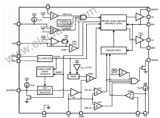
图1。LM27402方框图
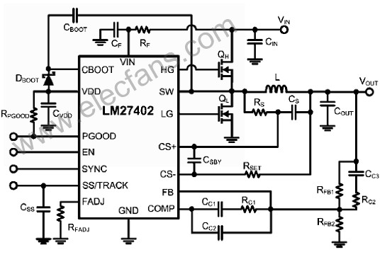
图2。LM27402典型连接图
图3。LM27402应用电路图:5V-12V输入,15V输出,输出电流20A,fsw= 300KHZ
所用元件列表:
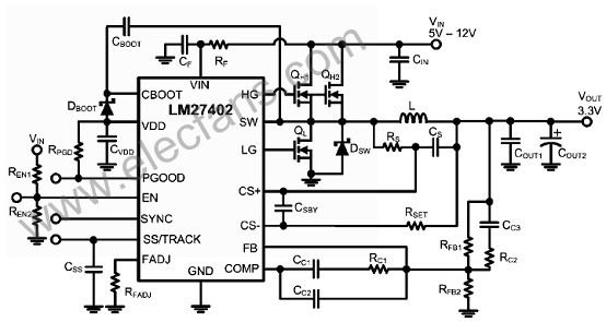
图4。LM27402应用电路图:5V-12V输入,3.3V输出,输出电流25A,fsw =300 kHz
所用元件列表:
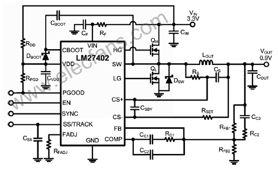
图5。 LM27402应用电路图:3.3V输入,0.9V输出,输出电流20A,fsw = 500 kHz
所用元件列表:
LM27402评估板
The LM27402 evaluation board represents a 20A typical application circuit. The application circuit is optimized for an input voltage of 12V. However, input voltage feed-forward technology allows the evaluation board to operate up to 20V while maintaining a stable output voltage of 1.5V at 20A.
Temperature compensated inductor DCR current limit circuitry provides a steady current limit setpoint. Extra MOSFET and input/output capacitor footprints are included to accommodate higher currents if desired. An externally set soft-start time of 10 ms provides a controlled monotonic startup. The LM27402 evaluation board also supports pre-biased startup and provides a tracking connection for power supply sequencing.
An external clock can be applied to change the switching frequency through an on board synchronization connection. PGOOD is externally pulled up to VDD and can be monitored via an on board terminal. Two extra terminals are included to provided a network analyzer connection for control loop stability analysis. The PCB measures 1.3” x 1.8” and includes input/output banana connectors for the input supply and load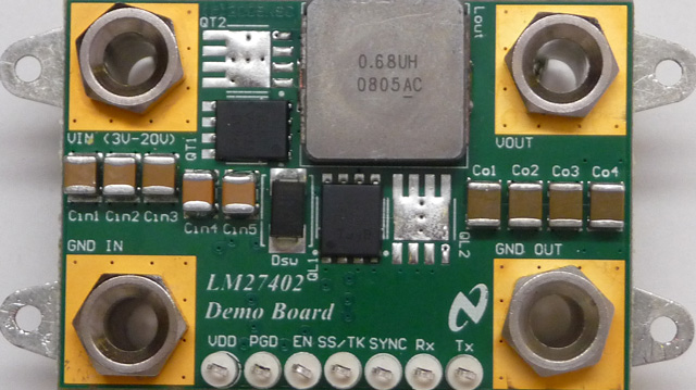
图6。LM27402评估板外形图
Evaluation Board Operating Specifications
• Input Voltage = 4.5V to 20V
• Output Voltage = 1.5V
• Output Current = 0A to 20A
图7。LM27402评估板电路图:VIN = 4.5V- 20V, VOUT = 1.5V, IOUT = 20A
LM27402评估板材料清单(BOM):