Current-loop signals, as opposed to voltage signals, are commonly used in industrial systems because they are much less subject to noise and relaTIvely indifferent to line length (because the current is unaffected by line resistance). The circuit of Figure 1 allows digital selecTIon between the two standard ranges of current-loop transmission common in industrial systems (0-20mA and 4-20mA).
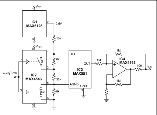
Figure 1. This circuit's single control input selects a current-loop range of 0-20mA or 4-20mA.
The analog switch (IC2) controls a resistive divider driven by the 2.5V reference (IC1), such that the AGND offset is either 0V or 0.4V, and the DAC's Δ voltage (OUT minus AGND) is either 2V or 1.6V. Thus,
for 0mA to 20mA, Δ = 2V and AGND = 0V;
for 4mA to 20mA, Δ = 1.6V and AGND = 0.4V.
The voltage-output D/A converter (IC3) drives a V/I converter (op amp IC4 and associated resistors) to produce the current loop. Because the DAC's output resistance in voltage mode is high (11kΩ), the resistor values are are made large to preserve accuracy. The op amp's output-drive capability is 80mA. To maintain good linearity, the reference voltage at OUT (IC3 pin 1) should not exceed 2V.
A similar version of this article appeared in the October 15, 2001 issue of EE Times magazine.