ApTIna公司的AP0100CS图像信号处理器(ISP)协同芯片用来与CMOS图像传感器一起设计使用,其目标市场是高性能模拟闭路电视(CCTV)市场。随着TV线分辨率(lines resoluTIon)朝向高于650 TVL/PH发展,并且宽动态范围(WDR)性能高达120dB,高性能CCTV市场领域的发展趋势是更高分辨率和更宽动态范围。ApTIna的AP0100CS可与其市场领先的低光照CMOS传感器产品结合,创建具有高分辨率和标准动态范围(SDR)或宽动态范围(WDR)的CCTV相机解决方案。
AP0100CS集成了ApTIna的先进图像处理管道(pipeline),具有令人惊叹的视频和低光照性能。借助用于宽动态范围图像再现(rendering)的高级局部色调映射(Advanced Local Tone Mapping, ALTM)功能,即使在非常困难的高对比度照明条件下也能够生成高质量的视频。AP0100CS集成了具有高级转换器功能的NTSC/PAL编码器,可以提供模拟CCTV市场所需的高TV线分辨率。
特性:
Up to 1.2Mp (1280x960) Aptina sensor support
45 fps at 1.2Mp, 60 fps at 720p
Optimized for operation with HDR sensors.
Color and gamma correction
Auto exposure, auto white balance, 50/60 Hz auto flicker detection and avoidance
Adaptive Local Tone Mapping (ALTM)
Programmable Spatial Transform Engine (STE).
Pre-rendered Graphical Overlay
Two-wire serial programming interface (CCIS)
Interface to low-cost Flash or EEPROM through SPI bus (to configure and load patches, etc.)
High-level host command interface
Standalone operation supported
Up to 5 GPIO
Fail-safe IO
Multi-Camera synchronization support
Integrated video encoder for NTSC/PAL with overlay capability and 10-bit I-DAC
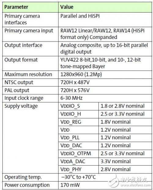
关键性能参数:
应用 :
IP cam and CCTV - HD
Enables CCTV -HD w/ MP sensor
Figure 1 shows the typical configuration of the AP0100CS in a camera system. On the host side, a two-wire serial interface is used to control the operation of the AP0100CS, and image data is transferred using the analog or parallel interface between the AP0100CS and the host. The AP0100CS interface to the sensor also uses a parallel interface.
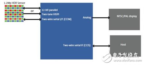
图1
典型并行配置
Figure 2: “Typical Parallel Configuration,” on page 7 and Figure 3: “Typical HiSPi Configuration,”
on page 8 show typical AP0100CS device connections.
All power supply rails must be decoupled from ground using capacitors as close as possible to the package.
The AP0100CS signals to the sensor and host interfaces can be at different supply voltage levels to optimize power consumption and maximize flexibility. Table 1 on page 9 provides the signal descriptions for the AP0100CS.
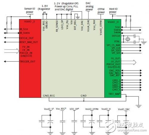
Figure 2: Typical Parallel Configuration
Note: 1. This typical configuration shows only one scenario out of multiple possible variations for this device.
2. Aptina recommends a 1.5kΩ resistor value for the two-wire serial interface RPULL-UP; however, greater
values may be used for slower transmission speed.
3. RESET_BAR has an internal pull-up resistor and can be left floating if not used.
4. The decoupling capacitors for the regulator input and output should have a value of 1.0uF. The capacitors
should be ceramic and need to have X5R or X7R dielectric.
5. TRST_BAR connects to GND for normal operation.
6. Aptina recommends that 0.1μF and 1μF decoupling capacitors for each power supply are mounted as
close as possible to the pin. Actual values and numbers may vary depending on layout and design consideration
典型HISPI(高速串行像素接口)配置:
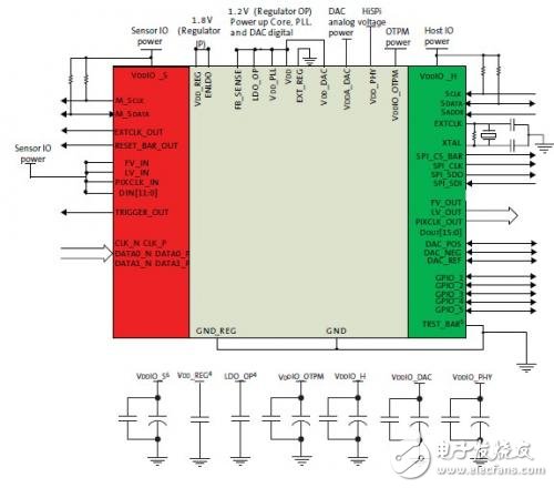
Figure 3: Typical HISPI Configuration
HiSPi and Parallel Connection
When using the HiSPi interface, the user should connect the parallel interface to VDDIO_S.When using the parallel interface, the HiSPi interface and power supply (VDD_PHY) can be left floating.