Chips are available to monitor and control venTIlaTIon fans. Less common are fan controllers for telecom applicaTIons, which must operate in electrically isolated environments with a supply voltage in the range 36V to 72V. As an example, the MAX6650 has the numerous control and monitor functions useful to system designers, but it resides on the secondary (low-voltage) side of the isolation barrier, and thus lacks the pulse width modulated (PWM) output often used to control high voltage fans.
It is possible to place a MAX6650 on the high-voltage side of the barrier and translate bidirectional I²C signals across to the low-voltage side, but an easier alternative is to keep the MAX6650 on the low-voltage side and use opto-isolators to translate two unidirectional signals (control and tachometer pulses) across the barrier (Figure 1).
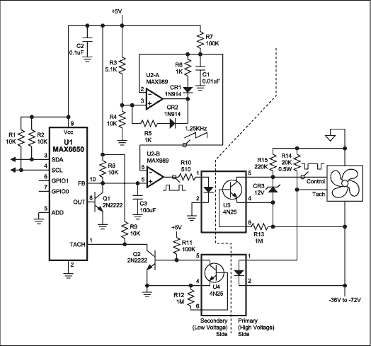
Figure 1. This telecom-system control circuit regulates fan speed according to a digital value stored in the controller (U1).
U1 and Q1 produce a DC control voltage at U1 pin 10. Comparators U2-A and U2-B then convert the DC voltage to a PWM signal as required by the fan. U2-A generates a 1.25kHz voltage ramp that climbs from approximately 1.2V to about 3.3V. U2-B compares this ramp to the control voltage, developing a PWM signal that is applied to the LED in opto-isolator U3. The phototransistor in U3 inverts the PWM signal and feeds it directly to the fan's control input, where the signal's duty cycle dictates rotational speed for the fan.
For feedback, the fan produces a tachometer pulse train consisting of two pulses per revolution. Those pulses drive the LED in opto-isolator U4, and U4's phototransistor delivers the signal to U1's TACH input. U1 then serves the OUT voltage as necessary to maintain the TACH frequency at a level corresponding to a value placed in U1's internal register. The system microprocessor (µP) precisely dictates the fan speed by writing to that register via the I²C bus.
The U1 control loop also compensates for factors such as variation in the fan's supply voltage. The µP can command U1 to do many other things, such as issuing an alert when the fan fails, turning the fan off, or turning the fan fully on (to check fan bearings by noting the resulting fan speed).
A similar version of this article appeared in the August 5, 2002 issue of EDN magazine.