High temperatures can destroy electronic components. That's why many electronic systems use temperature sensor ICs to monitor system heat levels and noTIfy the system of thermal problems. Most of these sensor ICs are relaTIvely sophisticated, and allow the system to read temperature values, program "thermostat" limits, and control other characteristics such as temperature conversion rate. Such temperature sensor ICs provide a high level of protection to heat-sensitive components, but their cost and the cost of developing software to support them can be too high for some very cost-sensitive systems.
This application note describes two reliable, low-cost circuits that can protect the most cost-sensitive systems from thermal damage. These circuits use temperature switch ICs, which are simple devices that behave like thermostats with logic outputs. They have no digital communications capability and in most cases require no system software development, and are therefore less expensive to purchase and less expensive to design into a system.They are most often used to detect high-temperature conditions and shut down power supplies to allow the system to cool.
An example is the MAX6501. This IC emulates a temperature sensor, voltage reference, and comparator. When the IC's temperature exceeds a factory-programmed value, the output asserts. Because it is available in a 5-lead SOT23 package, it can be located very close to thermal trouble spots.
Shutdown Based on PC Board Temperature
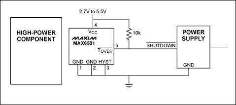
To use a local temperature sensor like the MAX6501 for system protection, use a circuit like Figure 1. The MAX6501's TOVER\ output controls the power supply for the high-power components. (TOVER\ goes low when the MAX6501's temperature threshold is exceeded.) Now two important choices need to be made:
Figure 1. The MAX6501 shown in this low-cost protection circuit monitors the temperature of the PC board near a high-power component. When temperature exceeds the MAX6501's preset trip threshold, TOVER\ goes low, shutting down the power supply to the high-power components.
Location.
If one component (for example a CPU or graphics processor) dissipates significantly more power than the other components on the board, locate the temperature switch as close to that high-power component as possible. If practical, the temperature switch should be near the ground traces for the target component so that heat from the target component will be conducted to the temperature switch through the metal traces. If there are two high-power components near each other, place the temperature switch between them.Trip Threshold.
The MAX6501 senses PC board temperature through its leads. Therefore, choose the trip threshold based on the maximum allowable board temperature at the temperature switch's location. You may have to determine this maximum temperature by characterization. Using the target high-power component's junction-to-case thermal resistance, calculate the case temperature when the die temperature is at its maximum (e.g. 125°C). Then operate the target component at a power dissipation level that brings its die temperature near the maximum. You can verify this by measuring the case temperature. Now measure the board temperature at the MAX6501's location. This will give a good estimate of the required trip temperature for the MAX6501.Shutdown Based on Target Component's Die Temperature
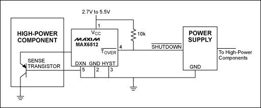
Some ICs that are capable of reaching high die temperatures include on-chip "diodes" (typically PNP emitter-base junctions) that can be used for direct sensing of die temperature. A remote-sensing temperature switch like the MAX6512 uses these sense junctions to signal when a programmed temperature has been exceeded.To use a remote temperature sensor like the MAX6512 for system protection, use a circuit like Figure 2. The MAX6512's TOVER\ output controls the power supply for the high-power components. (TOVER\ goes low when the MAX6512's temperature threshold is exceeded.)

Figure 2. The MAX6512 shown in this low-cost protection circuit monitors the die temperature of the high-power component using a sense transistor on the target die. When temperature exceeds the MAX6512's preset trip threshold, TOVER\ goes low, shutting down the power supply to the high-power components.