LED千足虫电路--The Millipede
Me and a friend are both trying to build a millipede. Because of obvious reasons, the millipede is NOT going to have 1000 feet!!! Instead, it's going to have 16 pager motors as feet. It will also have 3 MicroMotors to ''bend'' towards light, and a backup sensor.
FEATURES:
- 16 PagerMotors as feet
- 3 MicroMotors to seek light
- PhotoTrophic
- Obstacle avoidance
- Looks Cool!!!
MECHANICS:
Millipede is divided in four segments. Each segment (except the first one) is glued to a MicroMotor turned upside-down. The motor shaft is then glued to the next segment. Each segment can rotate left/right and has 2 PagerMotors on each side. This way, the millipede should turn towards the most lighted area. I've calculated that the waist motors should turn only 30o-45o every second or so. This means that I will need the motors to be 7-15 rpm. Candidates for this job can be the Lego MicroMotor, Solarbotics GM or BabyGM (unless I can get some MU915L Escaps!!!).
Weigth was a major concern since the whole bot was impulsed by pagermotors. The waist motors should weigth no more than 70g and the body (including electronics) is about <100g. Actually, it seems that 16 pagermotors are more than enough to move the bot!!!

ELECTRONICS:
I made up this circuit, as this is my first ''big'' BEAM creation I have no idea if it works properly. The upper 3 Ms are the Lego MicroMotors and the lower Ms should be the 16 PagerMotors. On the right, you can see the MicroMotors driver.

Here is the explanation:
1 This is the voltage divider. It divides voltage depending on which side is more iluminated, then, the schmitt changes the signal from a wave to a straight pulse.
2 The (usual) Nv only works when the input receives a HIGH, and that is the job of the schmitts. If the first schmitt outputs a HIGH the the lower strip of Nvs will work, the upper strip should stay calm because the second schmitt inverts the signal to a LOW. Thanks Math!!!
3 I can now be sure that there won't be 2 pulses on a same motor, and that when the first motor turns left (or right) the next one will also turn that same way, and the next and the next.... Only the first motor is affected by light, the others follow (in a wave pattern) the one before themselves. Since the millipede is moving forward while all this happens, a nice wave should appear when the bot has locked his path towards the light source.
4 This is the backup switch. When the bot bumps into something like... Hmm....anything, the cap is discharged trough the right schmitt. The (now LOW) output of the schmitt will reverse the PagerMotors, thus, reversing the whole bot.
5 This is the PagerMotors driver. I took the 4 transistor circuit design and modified it to be used with only one input signal. I know I won't be able to drive the 16 motors with 2N390X transistors, I used them in the schematic only because I need to find more powerful ones. Probably FETs?
6 As an extra (Yupeee), when the bot reverses it also makes the ''spinal column'' think that light is fully comming only from one direction. Because of this, when the millipede reverses, it also turns to one side all the body.
I still need to order the components (Let's just say there are not many 74**14s or 240s in Costa Rica), so the final version may be different than the drawings. I'm also thinking about using the Baby GMs that Solarbotics sell instead of the Lego MicroMotors. If you can help me with anything about the schematic, just email me.
相关热词:#灯电路
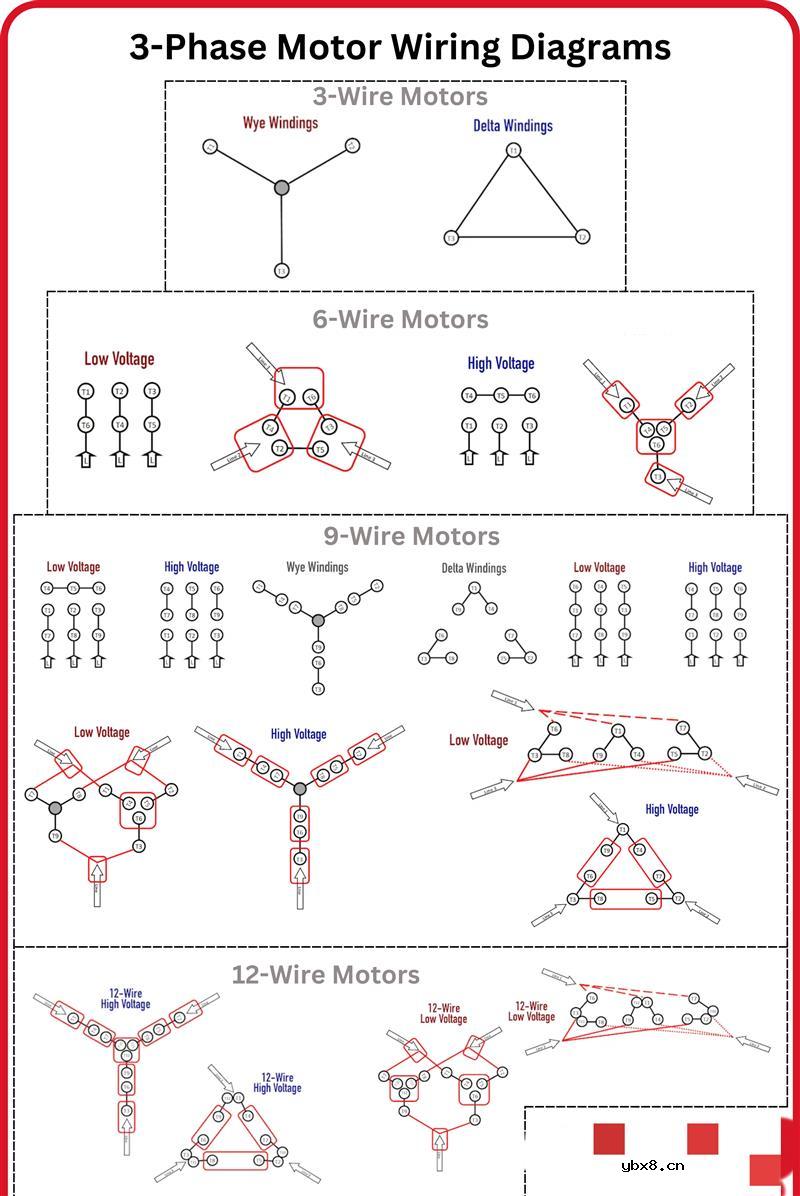 三相电机接线信息图
时间:2026-07-23
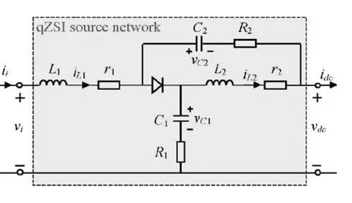 准 Z 源逆变器的设计
时间:2026-07-23
 关于阻容吸收器的简单介绍
时间:2026-07-23
S7-1200和CP343-1的Profinet通信方法
时间:2026-07-23
PDP(等离子显示),PDP是什么意思
时间:2026-07-23
光纤收发器的连接方式和作用
时间:2026-07-22
什么是电磁波?电磁波常见问题
时间:2026-07-22
 如何区分有源晶振和无源晶振
时间:2026-07-22
什么是“涡流”以及为什么它们对电机很重要...
时间:2026-07-22
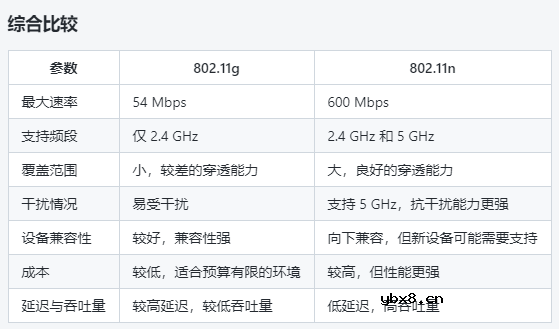 802.11g和802.11n的选择分析
时间:2026-07-21
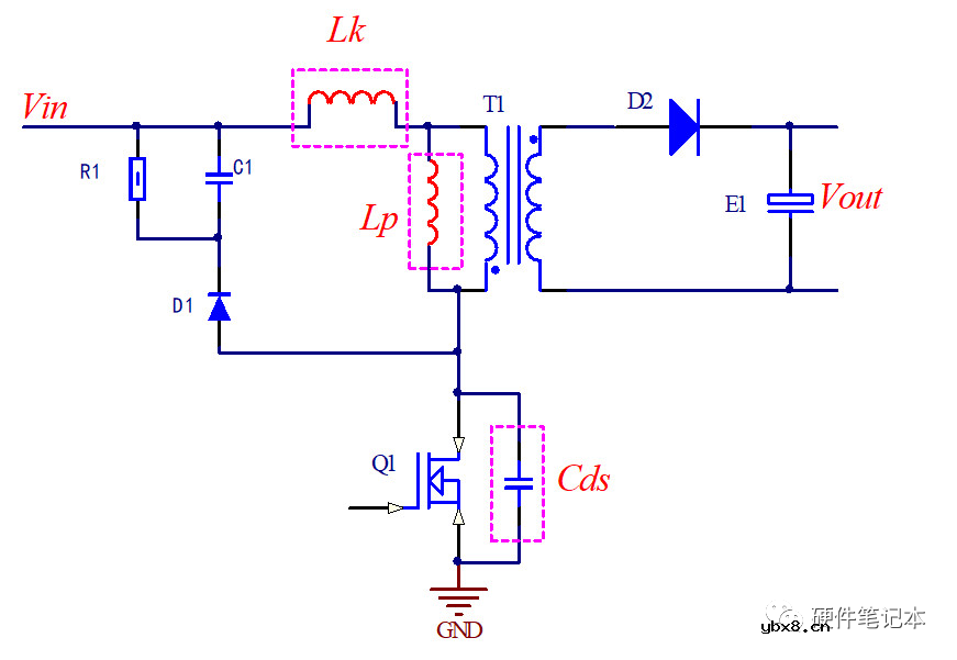 详解RCD钳位电路
时间:2026-03-08
三相异步电动机的拆装详讲
时间:2026-03-04
三相异步电动机原理
时间:2026-03-04
 基于逻辑门的构成解释如何完成任意逻辑的管...
时间:2026-03-08
 美的电磁炉电路图大全(六款美的电磁炉电路...
时间:2026-03-07
 彩灯电路
彩灯电路
时间:2026-03-05
 NE555的有趣电路设计分享
时间:2026-03-08
 从0学电路,万用表演示测量三极管方法
时间:2026-03-08
 光耦在电子电路中作用、关键参数详解
时间:2026-03-08
 H桥电机驱动电路解析
时间:2026-03-08