
自动风扇控制器电路,Automatic Fan Controller
Description
--------------------------------------------------------------------------------
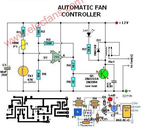
Th1, the 50K thermistor, is a standard type. Mine was a bar or rectangular looking thingy. Available from Tandy/Radio-Shack. Almost any type will do. I experimented with different models from 22K to 100K
and all worked fine after replacing the trimmer pot. The one used in the above circuit diagram was a 50K model. This 50K was measured at exactly 25 °C and with 10% tolerance. The resistance increases as the surrounding temperature decreases. Tolerance for my application (cooling a large powersupply coolrib) is 10%. Another name for this thing is 'NTC'. NTC stands for "Negative Temperature Coefficient" which means when the surrounding temperature decreases the resistance of this thermistor will increase. I replaced my thermistor for a 60K hermetically
sealed glass type since the environment for my application may contain corrosive particles which may affect performance on a future date. P1 is a regular Bourns trimmer and adjusts a wide range of temperatures for this circuit.
I used the 10-turn type for a bit finer adjustment but the regular type will work for your application.
R1 is a 'security' resistor just in case the trimmer pot P1 is adjusted all the way to '0' ohms. At which time the thermistor would get the full 12 volt and it will get so hot that it puts blisters on your fingers... :-)R3 feeds a bit of hysteresis back into the op-amp to eliminate relay 'chatter' when the temperature of the thermistor reaches its threshold point. Depending on your application and the type you use for Q1 and Re1, start with 330K or so and adjust its value downwards until your satisfied. The value of 150K shown in the diagram worked for me. Decreasing the value of R2 means more hysteresis, just don't use more then necessary. Or temporarily use a trimmer pot and read off the value. 120K worked for me.
Transistor Q1 can be a 2N2222(A), 2N3904, NTE123A, ECG123A, etc. Not critical at all. It acts only as a switch for the relay so almost any type will work, as long as it can provide the current needed to activate the relay's coil. D1, the 1N4148, acts as a spark arrestor when the contacts of the relay open and eliminates false triggering. For my application the 1N4148 was good enough since the tiny relay I used was only 1 amp.
However, you can use a large variety of diodes here, my next choice would be a regular purpose 1N4001 or something and should be used if your relay type can handle more then 1 amp. If you like to make your own pcb, try the one above. The pcb is fitted with holes for the relay but may not fit your particular relay. It was designed for a Aromat HB1-DC12V type.
The variety and model of relays is just to great. How to mount it then? Well, I left ample space on the pcb to mount your relay. You can even mount it up-side-down and connect the wires individually. Use Silicon glue, cyanoacrylate ester (crazy glue), or double-sided tape to hold the relay in place. Works well. Note that the pcb and layout is not according to the circuit diagram in regards to the hookup of the fans. The PCB measures approximately 1.5 x 3 inches (4.8 x 7.6mm) If you print the pcb to an inkjet printer it is probably not to scale. Try to fit a 8-pin ic socket on the printed copy to make sure it fits before making the pcb...
相关热词:#风扇
 什么是感应电机?什么是无刷电机?二者有何区...
时间:2026-10-23
多核DSP的多路同步时钟信号设计
时间:2026-10-23
什么是lcd12864?lcd12864的特性及其应用举例
时间:2026-10-23
 IoT无线连接基础知识
时间:2026-10-23
光是一种电磁波,那么光的频率是多少?
时间:2026-10-22
 DRAM简介
时间:2026-10-22
电容耦合是什么意思呀?
时间:2026-10-22
什么是单总线
时间:2026-10-21
STM32的CAN总线通信实现
时间:2026-10-21
什么是电源管理?有什么作用
时间:2026-10-20
 详解RCD钳位电路
时间:2026-03-08
三相异步电动机原理
时间:2026-03-04
 美的电磁炉电路图大全(六款美的电磁炉电路...
时间:2026-03-07
三相异步电动机的拆装详讲
时间:2026-03-04
 基于逻辑门的构成解释如何完成任意逻辑的管...
时间:2026-03-08
 彩灯电路
彩灯电路
时间:2026-03-05
 光耦在电子电路中作用、关键参数详解
时间:2026-03-08
 从0学电路,万用表演示测量三极管方法
时间:2026-03-08
 NE555的有趣电路设计分享
时间:2026-03-08
 H桥电机驱动电路解析
时间:2026-03-08