
LED或灯序电路--LEDs or Lamps Sequencer
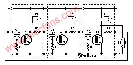
Parts:
R1______________1K5 1/4W Resistor
R2____________680R 1/4W Resistor (Optional, see text)
C1_____________47΅F 25V Electrolytic Capacitor
D1_____________LED any type
Q1___________BC337 45V 800mA NPN Transistor
P1_____________SPST Pushbutton
LP1____________Filament Lamp 12 or 24V (See text)
Comments:
The purpose of this circuit was to create a ring in which LEDs or Lamps illuminate sequentially. Its main feature is a high versatility: you can build a loop containing any number of LEDs or Lamps, as each illuminating device has its own small circuit.
The diagrams show three-stage circuits for simplicity: you can add an unlimited number of stages (shown in dashed boxes), provided the last stage output was returned to the first stage input, as shown.
P1 pushbutton purpose is to allow a sure start of the sequence at power-on but, when a high number of stages is used, it also allows illumination of more than one LED or Lamp at a time, e.g. one device illuminated and three out and so on.
After power-on, P1 should be held closed until only the LED or Lamp related to the module to which the pushbutton is connected remains steady illuminated. When P1 is released the sequencer starts: if P1 is pushed briefly after the sequence is started, several types of sequence can be obtained, depending from the total number of stages.
Notes:
If one LED per module is used, voltage supply can range from 6 to 15V.
You can use several LEDs per module. They must be wired in series and supply voltage must be related to their number.
Using 24V supply (the maximum permitted voltage), about 10 LEDs wired in series can be connected to each module, about 7 at 15V and no more than 5 at 12V.
The right number of LEDs can vary, as it is depending by their color and brightness required.
Using lamps, voltage supply can range from 9 to 24V. Obviously, lamp voltage must be the same of supply voltage.
In any case, lamps may also be wired in series, e.g. four 6V lamps wired in series can be connected to each module and powered by 24V supply.
If you intend to use lamps drawing more than 400mA current, BC337 transistors should be substituted by Darlington types like BD677, BD679, BD681, 2N6037, 2N6038, 2N6039 etc.
As Darlington transistor usually have a built-in Base-Emitter resistor, R1 may be omitted, further reducing parts counting.
Sequencer speed can be varied changing C1 value.
A similar design appeared in print about forty years ago. It used germanium transistors and low voltage lamps. I think the use of LEDs, silicon transistors, Darlington transistors and 24V supply an interesting improvement.
相关热词:
 什么是感应电机?什么是无刷电机?二者有何区...
时间:2026-10-23
多核DSP的多路同步时钟信号设计
时间:2026-10-23
什么是lcd12864?lcd12864的特性及其应用举例
时间:2026-10-23
 IoT无线连接基础知识
时间:2026-10-23
光是一种电磁波,那么光的频率是多少?
时间:2026-10-22
 DRAM简介
时间:2026-10-22
电容耦合是什么意思呀?
时间:2026-10-22
什么是单总线
时间:2026-10-21
STM32的CAN总线通信实现
时间:2026-10-21
什么是电源管理?有什么作用
时间:2026-10-20
 详解RCD钳位电路
时间:2026-03-08
三相异步电动机原理
时间:2026-03-04
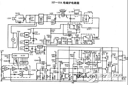 美的电磁炉电路图大全(六款美的电磁炉电路...
时间:2026-03-07
三相异步电动机的拆装详讲
时间:2026-03-04
 基于逻辑门的构成解释如何完成任意逻辑的管...
时间:2026-03-08
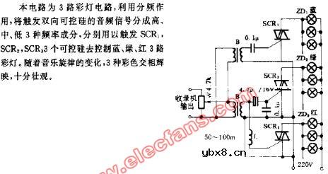 彩灯电路
彩灯电路
时间:2026-03-05
 光耦在电子电路中作用、关键参数详解
时间:2026-03-08
 从0学电路,万用表演示测量三极管方法
时间:2026-03-08
 NE555的有趣电路设计分享
时间:2026-03-08
 H桥电机驱动电路解析
时间:2026-03-08