红外数字温控风扇电路,IR Digital Thermostat for FAN
Introduction
--------------------------------------------------------------------------------
This circuit measures temperature in Celsius scale and displays it on an alphanumeric LCD screen
When temperature rise to 40 C an alarm is activated and at the same time a relay is also activated which
drives a fan to keep the temperature at a level.
Another feature of this circuit is that you can use the keys "1,2,3,4" of a Philips TV IR remote to turn on or off three relays, The key '4' is used to turn on or off the over temperature alarm.
Hardware
The brain of this circuit is AT89C51 microcontroller. LM35 is a 3 pin chip which is easily available in TO-92
package. LM35 can sense temperature from 0 C to 100 C but it gives analogue output the microcontroller does not understand analogue data, so ADC0804 (analogue to digital converter) is used to convert it to digital form.
This digital data is given to port 1 of microcontroller. (See the circuit diagram) this data is processed by microcontroller and temperature is displayed on lcd connected to port 2.The control pins of lcd are connected to port 0. port 0 also controls the relays and alarm.

The ULN2003 chip is used to drive the relays because the microcontroller pins don't have enough current to drive them. so relays cant be connected to microcontroller pins directly further more the relays are inductive load and reverse current is generated in them. Pin 1 to 7 are the inputs and 10to 16 are respective outputs. Pin 8 is ground and pin 9 is connected to the output of 7808 voltage regulator.
The 7805 voltage regulator drives rest of the circuit. I used a standard buzzer driven by LM555 timer/Oscillator chip. The chip is wired as a monostable multivibrator and at its output (i.e. pin no 3) a buzzer is connected.
Use any IR module and connect its Data out to pin 10 of microcontroller. The Relay connected to pin 13 of ULN2003 turns on when temp rises above 40 C so connect the fan to this relay.
Hardware
--------------------------------------------------------------------------------
As this circuit has many components I advice don't use Vero boards or point to point boards.
Use a standard pcb. A pcb file is included in the zip file it opens with a software called EAGLE You can download the demo version here its quiet simple and easy to use. So print the pcb on a glossy paper. now place the glossy paper on the pcb. The print should be on the copper side now use an iron to transfer the print on the pcb. After you are done dip the pcb in any enchant I used FeCl3 (ferric chloride). When your pcb is ready pour lots of water to remove any FeCl3 and remove the print using steel wool. Now drill holes and place components.
download the zip folder it contains the images of completed
project, hex file circuit diagram and pcb file.
click here for pcb, Circuit diagram and hex file in a zip
Click the picture below for a Larger View.

相关热词:#红外
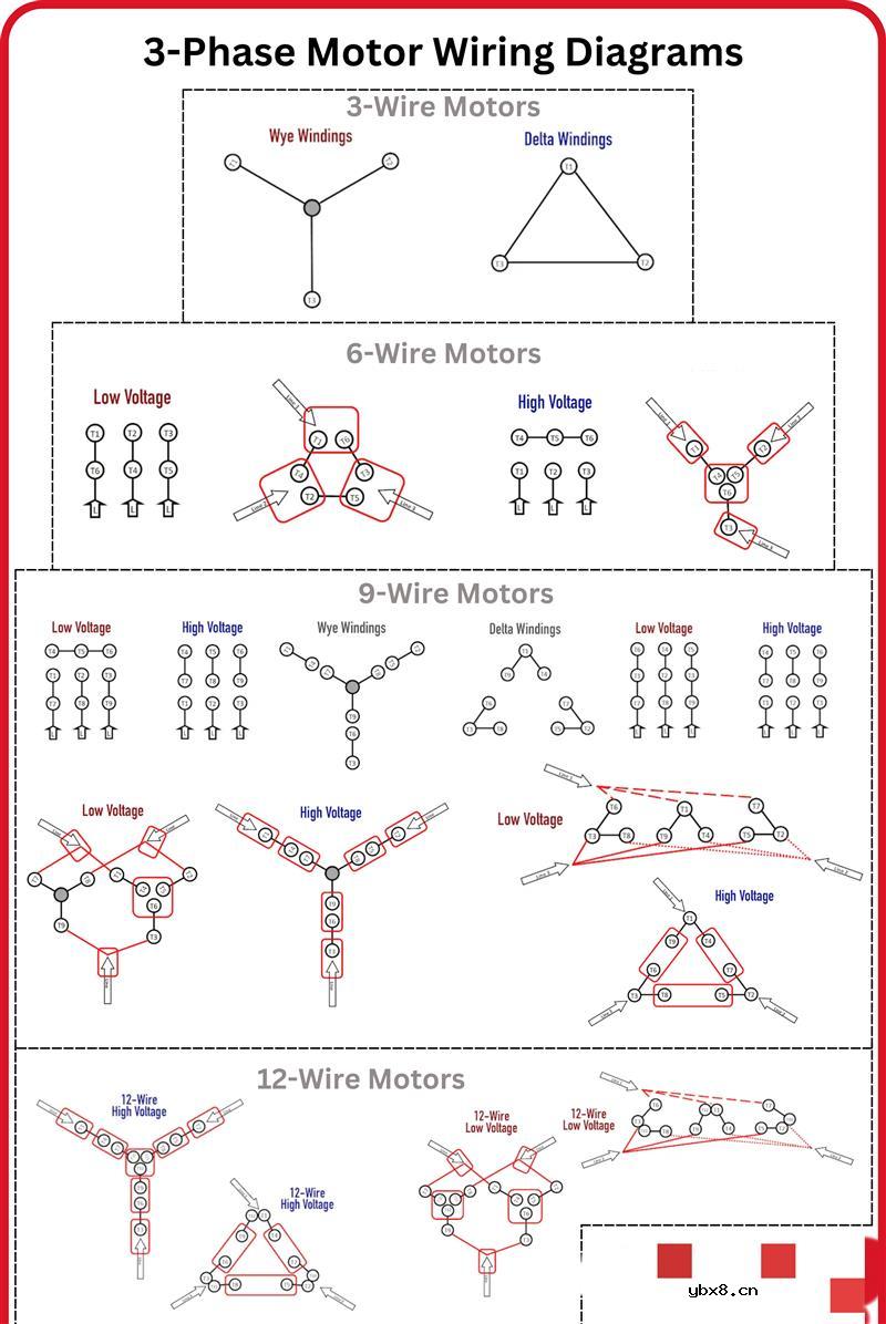 三相电机接线信息图
时间:2026-07-23
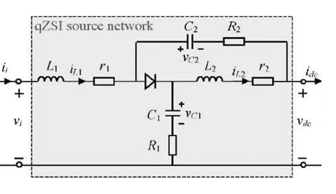 准 Z 源逆变器的设计
时间:2026-07-23
 关于阻容吸收器的简单介绍
时间:2026-07-23
S7-1200和CP343-1的Profinet通信方法
时间:2026-07-23
PDP(等离子显示),PDP是什么意思
时间:2026-07-23
光纤收发器的连接方式和作用
时间:2026-07-22
什么是电磁波?电磁波常见问题
时间:2026-07-22
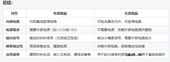 如何区分有源晶振和无源晶振
时间:2026-07-22
什么是“涡流”以及为什么它们对电机很重要...
时间:2026-07-22
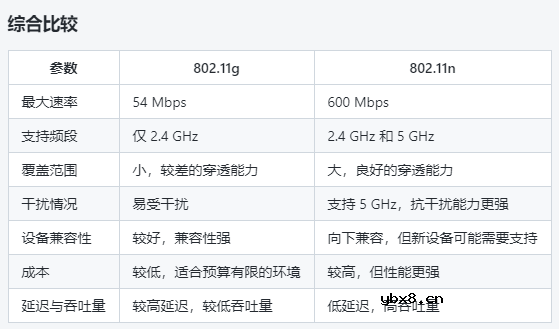 802.11g和802.11n的选择分析
时间:2026-07-21
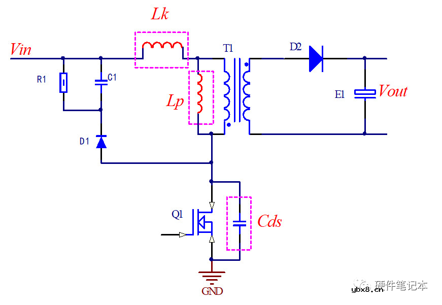 详解RCD钳位电路
时间:2026-03-08
三相异步电动机的拆装详讲
时间:2026-03-04
三相异步电动机原理
时间:2026-03-04
 基于逻辑门的构成解释如何完成任意逻辑的管...
时间:2026-03-08
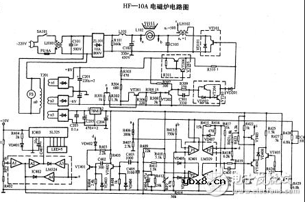 美的电磁炉电路图大全(六款美的电磁炉电路...
时间:2026-03-07
 彩灯电路
彩灯电路
时间:2026-03-05
 NE555的有趣电路设计分享
时间:2026-03-08
 从0学电路,万用表演示测量三极管方法
时间:2026-03-08
 光耦在电子电路中作用、关键参数详解
时间:2026-03-08
 H桥电机驱动电路解析
时间:2026-03-08