
正的逻辑探针电路,Logic Probe Plus
This project is based on a probe logic states, capable of measuring levels from TTL (5v) to state levels of PLC's (24v). For this we have employed the use of the PIC 12F683 microcontroller, which by its nature is capable of operating at low voltages, in this case 3vcc, besides having analog inputs and internal oscillator.
The circuit is supplemented by an input stage which will adapt the signal to the levels between the microprocessor is able to work and another output stage that will visually show the state in which the point is measured.
The input stage to include a voltage divider between R3 D5 and D1, their role is to establish a fixed value (/ - 2.80) for the input of the microcontroller which means that is in a state of high impedance, ie without input signal. When we apply the input signal DATA IN this will vary the voltage drop at point H so that the reading as we discriminate if this is higher or lower than the reference voltage.
The output stage is made up 3 LED (yellow = high impedance, Green = Red = logic 1 and logic 0).
The program also has an internal timer to approximately 3 minutes between the microcontroller in sleep mode in which consumption will be minimal, to save the battery. And it will reactivate the program until you press the button, starting over allowing timing and take readings we require.
Focusing on the program of the microprocessor, this is configured to work with internal oscillation 4Mhz and configuring its pin so that analog reading take from point H by the GP1 pin, which is defined for a resolution of 10 bits, pin GP2 will also be defined as input and will be connected through a resistor (PULL UP) and a secondary switch to ground, which will be responsible for collecting the press that forced the interruption level change in GP2 While the interruption occurs loads a value (2000) as a timer to make a loop past work and this time will be placed the microcontroller in sleep mode.
The program is also complimented inizialización a function which shows the blinking leds, to argue that this in active process and that at the end of this sequence we can take appropriate measures.
The bulk of the program is effected by a loop of reading and comparing the reading which collects and compares GP1 activating the corresponding output.
In order to function alone is sufficient to connect the ground wire to any metal part of the chassis or failing to ground.
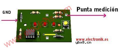
the code is open and available to anyone who
want, just send an e-mail and ask.
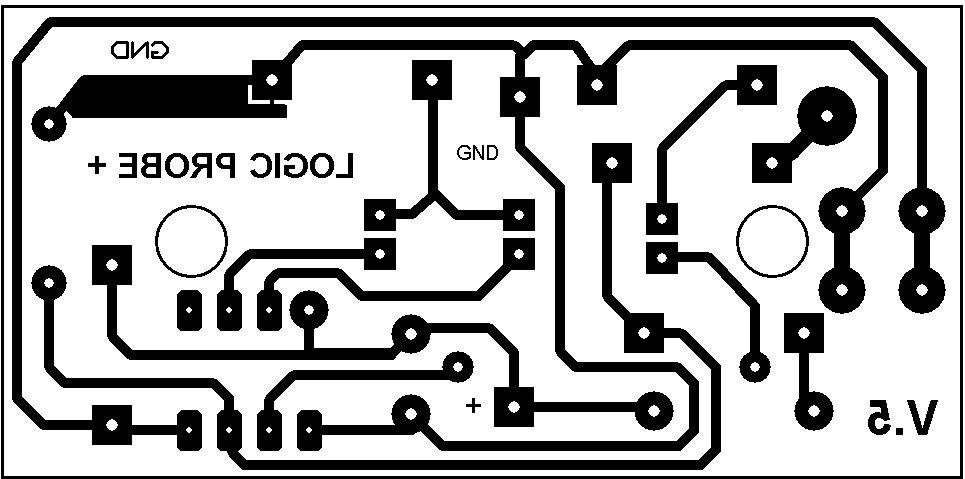
PCBs
相关热词:#探针
 什么是感应电机?什么是无刷电机?二者有何区...
时间:2026-10-23
多核DSP的多路同步时钟信号设计
时间:2026-10-23
什么是lcd12864?lcd12864的特性及其应用举例
时间:2026-10-23
 IoT无线连接基础知识
时间:2026-10-23
光是一种电磁波,那么光的频率是多少?
时间:2026-10-22
 DRAM简介
时间:2026-10-22
电容耦合是什么意思呀?
时间:2026-10-22
什么是单总线
时间:2026-10-21
STM32的CAN总线通信实现
时间:2026-10-21
什么是电源管理?有什么作用
时间:2026-10-20
 详解RCD钳位电路
时间:2026-03-08
三相异步电动机原理
时间:2026-03-04
 美的电磁炉电路图大全(六款美的电磁炉电路...
时间:2026-03-07
三相异步电动机的拆装详讲
时间:2026-03-04
 基于逻辑门的构成解释如何完成任意逻辑的管...
时间:2026-03-08
 彩灯电路
彩灯电路
时间:2026-03-05
 光耦在电子电路中作用、关键参数详解
时间:2026-03-08
 从0学电路,万用表演示测量三极管方法
时间:2026-03-08
 NE555的有趣电路设计分享
时间:2026-03-08
 H桥电机驱动电路解析
时间:2026-03-08