电感仪表适配器电路,Inductance meter adapter

All resistances are in ohms
7805 positive regulator 5v o/p
2SC9018 is a high frequency transistor with FT of 1.1 Ghz . you need high frequency transistors in the circuit where it is used in case you want to substitute for it.
I guess 2n2857, 2n5179 ,BF180 can be substituted
The following circuit enables me to measure inductance of the inductor labeled LX which is the inductance to be measured. The o/p of the circuit is a TTL square wave whose frequency relates to the inductance being measured.
The inductance meter adapter output is connected to a frequency meter and the inductance is calculated from the frequency.Hence you need a frequency meter and some calculation to get your inductor value.
HOW IT WORKS
The heart of the circuit is the buffer colpitts oscillator(the first stage) which resonates with the unknown inductance to give a Sine wave of a particular frequency .
The frequency of the sine wave is a function of the unknown inductance and the four 1000pF capacitors.
The output sine wave is amplified by the second transistor and is then rectified by the capacitor and diode combination that Follows.
The rectified sine wave now having only positive excursions is buffered by the third transistor and is then fed to the 74ls393
Counter ic which is configured as a divide by 256 counter.
The output of the ic pin 6 and ground is connected to the frequency meter.
NOTES
The 7805 regulator powers the IC and the last 2 transistors
The circuit operates from a 9V battery which also feeds the regulator
The Ic consists of two counters in one package of 14 pins hence you need just one.
PIN 14 is VCC and PIN 7 is ground
The ic is TTl IC
PERFORMANCE AND GETTING YOUR READING
My own digital meter can read frequency so I use it to take the reading.
I programmed my calculator to get me the inductance value from the reading. A simple computer programme can do this as well.
Actual frequency= Frequency reading*256 (the counters have scaled down the frequency by 256 times)
Actual frequency = f=

So the last equation allows you to solve for the value of the inductance Lx which will be in microhenries.
ADDITIONAL COMMENTS
This inductance measuring scheme works well for inductances of even low values less than 1uH. However the lower
Values could have error due to the circuit including test lead inductance. The circuit is that sensitive. I play with some tricks to get around this which I will discuss later if people are interested in the circuit. I wish it was a stand alone unit but here in my country NIGERIA(IN WEST AFRICA) and my city Ibadan there are no fancy PICS or Digital displays to make it a stand alone unit so I just have to make do with Simple IC’S and transistors.
Sorry the equations don’t look too neat I hope you get them though.
Any comments about this circuit can be mailed to me and I hope somebody finds it interesting enough to construct And possibly make a stand alone unit with microprocessors or PICS and displays that I haven’t got. Thanks to Bernardo Dimacali for helping me put the equation in a good and clear form.
lm7805中文资料 http://www.elecfans.com/soft/78/223/2008/200805053492.html
相关热词:#Inductance
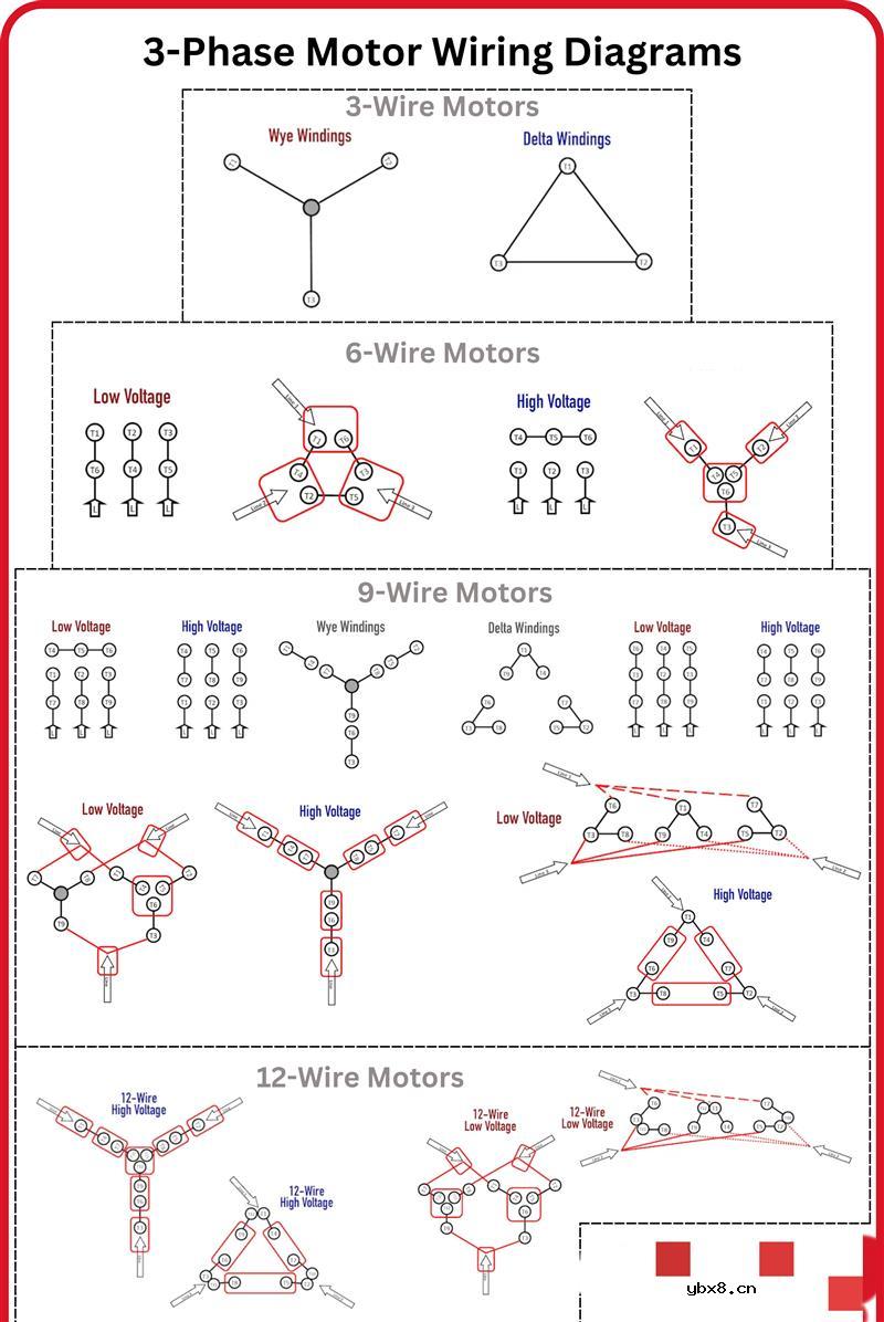 三相电机接线信息图
时间:2026-07-23
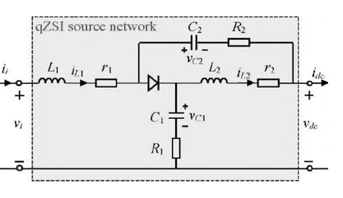 准 Z 源逆变器的设计
时间:2026-07-23
 关于阻容吸收器的简单介绍
时间:2026-07-23
S7-1200和CP343-1的Profinet通信方法
时间:2026-07-23
PDP(等离子显示),PDP是什么意思
时间:2026-07-23
光纤收发器的连接方式和作用
时间:2026-07-22
什么是电磁波?电磁波常见问题
时间:2026-07-22
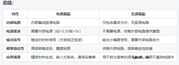 如何区分有源晶振和无源晶振
时间:2026-07-22
什么是“涡流”以及为什么它们对电机很重要...
时间:2026-07-22
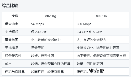 802.11g和802.11n的选择分析
时间:2026-07-21
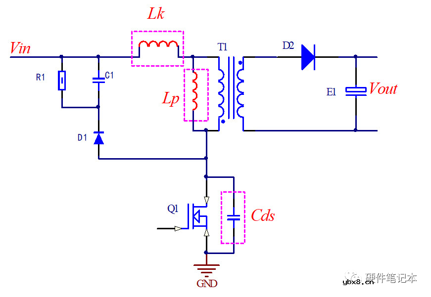 详解RCD钳位电路
时间:2026-03-08
三相异步电动机的拆装详讲
时间:2026-03-04
三相异步电动机原理
时间:2026-03-04
 基于逻辑门的构成解释如何完成任意逻辑的管...
时间:2026-03-08
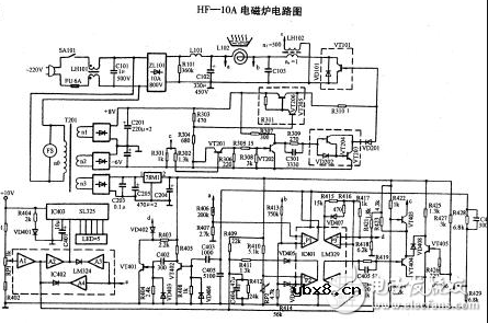 美的电磁炉电路图大全(六款美的电磁炉电路...
时间:2026-03-07
 彩灯电路
彩灯电路
时间:2026-03-05
 NE555的有趣电路设计分享
时间:2026-03-08
 从0学电路,万用表演示测量三极管方法
时间:2026-03-08
 光耦在电子电路中作用、关键参数详解
时间:2026-03-08
 H桥电机驱动电路解析
时间:2026-03-08