Low-Cost, Dual SCART SoluTIon for Set-Top Boxes Also Has OpTIonal Kanal+ Support
Abstract: This applicaTIon note describes how the MAX9655 video filter amplifier can be used to realize a low-cost, dual SCART switch soluTIon. The note also explains how Kanal+ can be supported by adding an analog multiplexer.
Introduction
Kanal+ support allows a VCR to record audio and video signals captured by both the STB and TV without changing SCART connections on the back of the TV, STB, and VCR.
The basic connection shown in the application note allows audio and video signals captured only by the STB to be recorded by the VCR. The Kanal+ support shown here allows audio and video signals captured by the TV to be recorded by the VCR as well, without changing the connections on the back of the TV. Using this solution, the TV sends the audio and video signals back to the STB, which again sends those signals to the VCR in standby mode.
The MAX9655 video only SCART switch, offers engineers a new approach for designing the audio and video switching circuitry in dual SCART set-top boxes. The MAX9655 has 21mA (typ) and 45mA (max, guaranteed) current consumption and ±2kV ESD protection at the pin level, which allows the design of the next-generation "green" and robust set-top boxes.
Traditional set-top-box designs use either an integrated SCART switch or a 4- or 5-channel video filter amplifier. Whether integrated or discrete, each of those solutions has some advantages and disadvantages. Designs using integrated SCART switches are more expensive but are easy to design, feature low-power operation, require a small PCB (PC board) area, and do not have audio clicks or pops. Therefore, integrated SCART switches are better suited for high-end set-top boxes, personal video recorders, etc. Discrete solutions that use a stand-alone video filter amplifier are less expensive, and thus better for high-volume, low-to-mid-end set-top boxes. However, some of the advanced features in integrated SCART switches will not be available in these less costly discrete designs.
Maxim's new family of video ony scart switches, the MAX9655 and MAX9656, offers both the performance benefits of the integrated SCART designs and the lower cost of discrete solutions. The MAX9655 featured here is a very cost-competitive solution compared with discrete video filters. Its has most of the high-end features of integrated SCART devices like low power, small PCB area, and minimal external components.
This application note discusses how to use MAX9655 in two different configurations commonly encountered in set-top-box designs. The first solution is for the lowest cost, lowest component count, dual SCART set top boxes which do not support Kanal+. The second design shows how Kanal+ can be supported by simply adding an optional 4053 analogue multiplexer.
Basic SCART Solution
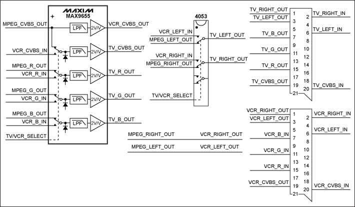
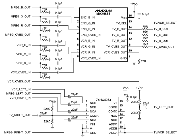
Figure 1 shows the basic application block diagram. The MAX9655 is used with a simple 4053-type analogue multiplexer to form an audio/video switching circuit for a dual SCART set-top box. Figure 3 (below) shows the corresponding schematics.
Figure 1. Basic block diagram uses a MAX9655 and a 4053 for dual SCART solution.
The CVBS and RGB signals from both the MPEG decoder chip and the VCR SCART are AC-coupled to the inputs of the MAX9655. The MAX9655 selects the set of video signals that are sent to the TV SCART according to the status of the TV/VCR_SELECT pin, which is controlled by the software. When the TV/VCR_SELECT pin is low, the CVBS and RGB outputs of the MPEG decoder chip are selected, filtered, and then amplified by 2V/V constant-gain video amplifiers before they are sent to the TV SCART. When the TV/VCR_SELECT control pin is high, the CVBS and RGB signals coming from the VCR SCART are selected, filtered, amplified, and then sent to the TV SCART.
The 4053 analogue multiplexer selects the appropriate audio signals. Audio outputs of the MPEG decoder, together with the audio signals coming from the VCR SCART, are applied to the 4053 analogue multiplexer. When the TV/VCR_SELECT control pin is low, the audio outputs of the MPEG decoder chip are sent to the TV SCART. When this control pin is high, audio signals coming from the VCR SCART are sent to the TV SCART. The 4053 analogue multiplexer must be powered from an appropriate VCC supply to allow 2VRMS audio to pass through the switches. The input audio signals must also be biased to an appropriate level before or after the analogue switch. This allows the negative portion of the audio signal to pass through the switch without any distortion. The switched audio signals must be AC-coupled before they are sent to the TV SCART.
The CVBS and audio outputs of the MPEG decoder chip are always sent to the VCR SCART. The CVBS and audio signals coming from the TV SCART are not processed.
The design in Figure 1 works well for a basic dual SCART set-top box. The MAX9655 handles all the switching, filtering, and amplifying requirements for the video signals. The 4053 analogue multiplexer functions as an audio switch. One of the analogue switches in the 4053 IC is unused and available for another task like switching pin 8 or pin 16 signals. The state of the TV/VCR_SELECT control pin changes when the set-top box goes into, or out of, standby mode.
Optional Support for Kanal+
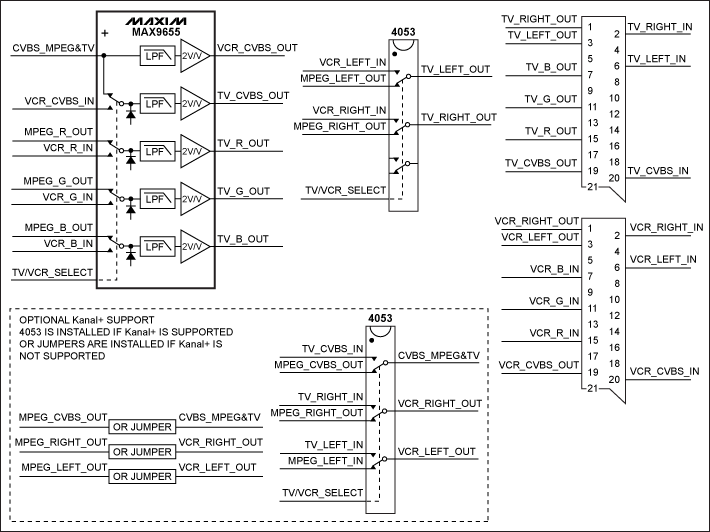
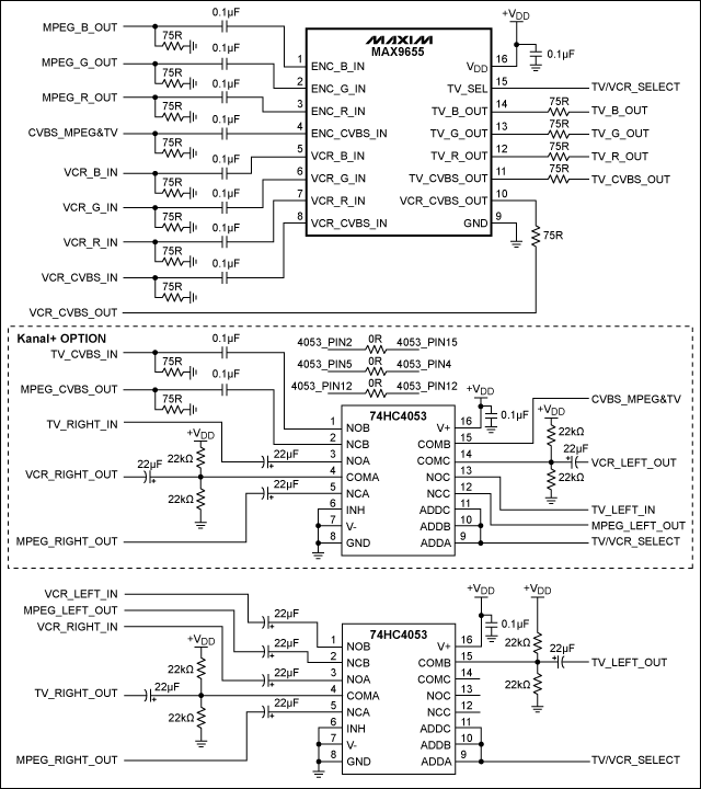
Figure 2 shows how Kanal+ support can be provided by adding the circuitry inside the dotted line. Figure 4 shows the corresponding schematics.
Figure 2. Optional Kanal+ support is provided by adding a second 4053 multiplexer to the MAX9655 design in Figure 1.
To provide Kanal+ support, a second 4053 multiplexer is used. In Figure 2 an analogue switch in the second 4053 (bottom) device selects between the CVBS output of the MPEG decoder chip and the CVBS input coming from the TV SCART. The output of this switch, which is called CVBS_MPEG&TV in Figure 2, is then applied to the input of the MAX9655, which is the fourth pin.
When the set-top box is not in the standby mode, the TV/VCR_SELECT control pin is set low. During this condition, the optional 4053 selects MPEG_CVBS_OUT and sends this signal to the MAX9655. Because TV/VCR_SELECT is low, the MAX9655 also selects this signal, and sends it to both the TV SCART and the VCR SCART after filtering and amplifying. The net result is that the CVBS and RGB video outputs of the MPEG decoder are sent to both the TV SCART and the VCR SCART—the expected behavaior when a set-top box operates normally.
When the set-top box is in standby mode, TV/VCR_SELECT is set high. In this mode the bottom 4053 selects TV_CVBS_IN and sends it to the MAX9655. Because TV/VCR_SELECT is set high, TV_CVBS_IN can only be sent to VCR_CVBS_OUT; TV_CVBS_OUT is connected to the VCR_CVBS_IN, which is what Kanal+ requires.
Summary
The designs in Figures 1 and 2 illustrate how the MAX9655 can be used in all dual SCART set-top boxes. The circuit in Figure 1 is recommended if Kanal+ support is not required; the circuit in Figure 2 is recommended if Kanal+ is required. According to the Kanal+ requirement, an additional 4053 is assembled or three jumpers are assembled.
All video inputs to the MAX9655 must be AC-coupled, as the input sync-tip clamps will set the internal DC level. The only exception to this is CVBS_MPEG&TV input in the Kanal+ configuration. Because a DC bias is needed for the selected video to pass through the external 4053 analogue switch without any distortion, the DC level set by the input sync-tip clamps of MAX9655 can be used for this purpose. The CVBS_MPEG&TV can be DC-coupled to MAX9655, and then the video inputs TV_CVBS_IN and MPEG_CVBS_OUT listed in Table 1 must be AC coupled to the 4053.
Table 1. SCART Outputs According to the TV/VCR_SELECT
Both of these solutions use a MAX9655 low-power video switch, filter, and amplifier designed for dual SCART set-top boxes. The MAX9655 operates from a single 3.3V supply. Its 21mA (typ) and 45mA (max, guaranteed) current consumption results in a low-power standby mode which is required by the next generation of "green" set-top boxes. The device provides ±2kV ESD protection, which will actually be better after 75Ω resistors are installed.

Figure 3. Schematics for the basic dual scart switch in Figure 1.

Figure 4. Schematics for the dual scart switch with Kanal+ support in Figure 2.