TI MSP430F543x超低功耗开发方案
关键词:MCU, 超低功耗, MSP430, RISC CPU,DMA,
摘要:TI公司的MSP430F543x系列是超低功耗微控制器,每个器件有不同的外设,以适应不同的应用. MSP430F543x系列具有功能强大的16位RISC CPU,16位寄存器和能提供最大代码效率的常数发生器. MSP430F543x(A) 和MSP430F541x(A)系列能配置成三个16位计时器,高性能16位ADC和多达4个通用串行通信接口(USCI),硬件乘法器,DMA,带告警功能的实时时钟模块以及多达87个I/O引脚.该系列广泛应用在模拟和数字传感器系统,数字马达控制,遥控,自动调温设备,数字计时器以及手持测量仪表等.本文介绍MSP430F543x的主要性能,方框图以及MSP430F543x 100引脚目标板MSP-TS430PZ5X100的主要性能及电路图和.MSP-FET430UIF USB接口模块电路图.
TI公司的MSP430F543x系列是超低功耗微控制器,每个器件有不同的外设,以适应不同的应用. MSP430F543x系列具有功能强大的16位RISC CPU,16位寄存器和能提供最大代码效率的常数发生器. MSP430F543x(A) 和MSP430F541x(A)系列能配置成三个16位计时器,高性能16位ADC和多达4个通用串行通信接口(USCI),硬件乘法器,DMA,带告警功能的实时时钟模块以及多达87个I/O引脚.该系列广泛应用在模拟和数字传感器系统,数字马达控制,遥控,自动调温设备,数字计时器以及手持测量仪表等.本文介绍MSP430F543x的主要性能,方框图以及MSP430F543x 100引脚目标板MSP-TS430PZ5X100的主要性能及电路图和.MSP-FET430UIF USB接口模块电路图.
The Texas Instruments MSP430 family of ultralow-power microcontrollers consists of several devices featuring different sets of peripherals targeted for various applicaTIons. The architecture, combined with five low power modes is optimized to achieve extended battery life in portable measurement applications. The device features a powerful 16-bit RISC CPU, 16-bit registers, and constant generators that contribute to maximum code efficiency.
The digitally controlled oscillator (DCO) allows wake-up from low-power modes to active mode in less than 5 μs. The MSP430F543x(A) and MSP430F541x(A) series are microcontroller configurations with three 16-bit timers, a high performance 12-bit analog-to-digital (A/D) converter, up to four universal serial communication interfaces (USCI), hardware multiplier, DMA, real time clock module with alarm capabilities, and up to 87 I/O pins.
Typical applications for this device include analog and digital sensor systems, digital motor control, remote controls, thermostats, digital timers, hand-held meters, etc.
The MSP430X CPU incorporates features specifically designed for modern programming techniques such as calculated branching, table processing and the use of high-level languages such as C. The MSP430X CPU can address a 1-MB address range without paging. The MSP430X CPU is completely backwards compatible with the MSP430 CPU.
The MSP430X CPU features include:
• RISC architecture
• Orthogonal architecture
• Full register access including program counter, status register and stack pointer
• Single-cycle register operations
• Large register file reduces fetches to memory.
• 20-bit address bus allows direct access and branching throughout the entire memory range without paging.
• 16-bit data bus allows direct manipulation of word-wide arguments.
• Constant generator provides the six most often used immediate values and reduces code size.
• Direct memory-to-memory transfers without intermediate register holding.
• Byte, word, and 20-bit address-word addressing
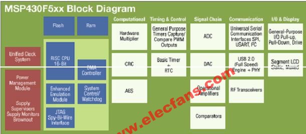
图1. MSP430F543x方框图
MSP430F543x主要特性:
Low Supply-Voltage Range
2.2 V to 3.6 V MSP430F543x, MSP430F541x
1.8 V to 3.6 V MSP430F543xA, MSP430F541xA
Ultralow Power Consumption
Active Mode (AM): 165 μA/MHz
Standby Mode (LPM3 RTC Mode): 2.6 μA
Off Mode (LPM4 RAM Retention): 1.6 μA
Shutdown Mode (LPM5): 0.1 μA
Wake-Up From Standby Mode in Less Than 5 μs
16-Bit RISC Architecture
Extended Memory
Up to 18-MHz System Clock MSP430F543x, MSP430F541x
Up to 25-MHz System Clock MSP430F543xA, MSP430F541xA
Flexible Power Management System
Fully Integrated LDO With Programmable Regulated Core Supply Voltage
Supply Voltage Supervision, Monitoring, and Brownout
Unified Clock System
FLL Control Loop for Frequency Stabilization
Low-Power/Low-Frequency Internal Clock Source (VLO)
Low-Frequency Trimmed Internal Reference Source (REFO)
32-kHz Crystals
High-Frequency Crystals up to 25 MHz
16-Bit Timer0_A5 With Five Capture/Compare Registers
16-Bit Timer1_A3 With Three Capture/Compare Registers
16-Bit Timer_B7 With Seven Capture/Compare Shadow Registers
Up to Four Universal Serial Communication Interfaces
Enhanced UART Supporting Auto-Baudrate Detection
IrDA Encoder and Decoder
Synchronous SPI
I2C™
12-Bit Analog-to-Digital (A/D) Converter
Internal Reference
Sample-and-Hold
Autoscan Feature
12 External Channels, 4 Internal Channels
Hardware Multiplier Supporting 32-Bit Operations
Serial Onboard Programming, No External Programming Voltage Needed
Three Channel Internal DMA
Basic Timer With Real Time Clock Feature
Family Members Include:
MSP430F5438, MSP430F5438A(1)
256KB+512B Flash Memory
16KB RAM
Four Universal Serial Communication Interfaces
MSP430F5436, MSP430F5436A(1)
192KB+512B Flash Memory
16KB RAM
Four Universal Serial Communication Interfaces
MSP430F5419(1), MSP430F5419A(1)
128KB+512B Flash Memory
16KB RAM
Four Universal Serial Communication Interfaces
MSP430F5437(1), MSP430F5437A(1)
256KB+512B Flash Memory
16KB RAM
Two Universal Serial Communication Interfaces
MSP430F5435(1), MSP430F5435A(1)
192KB+512B Flash Memory
16KB RAM
Two Universal Serial Communication Interfaces
MSP430F5418(1), MSP430F5418A(1)
128KB+512B Flash Memory
16KB RAM
Two Universal Serial Communication Interfaces
MSP430F543x 100引脚目标板MSP-TS430PZ5X100
MSP430F5xx 100-Pin Socket Target Board MSP-TS430PZ5X100,
The MSP-FET430U5x100 is a powerful flash emulation tool (FET) that includes the hardware and software required to quickly begin application development on the MSP430 MCU. It includes a ZIF socket target board (MSP-TS430PZ5x100) and a USB debugging interface (MSP-FET430UIF) used to program and debug the MSP430 in-system through the JTAG interface or the Spy Bi-Wire (2-wire JTAG) protocol. The flash memory can be erased and programmed in seconds with only a few keystrokes, and since the MSP430 flash is ultra-low power, no external power supply is required.
The debugging tool interfaces the MSP430 to the included integrated software environment and includes code to start your design immediately. The included MSP-TS430PZ5x100 development board supports all MSP430F5xx flash parts in a 100-pin TQFP package (TI package code: PZ).
The 100-pin socket target board (MSP-TS430PZ5x100) is also available standalone without the additional debugging interface.
MSP-TS430PZ5X100主要特性:
USB debugging interface (MSP-FET430UIF) connects a flash-based MSP430 MCU to a PC for real-time, in-system programming and debugging
Technical specifications:
Software configurable supply voltage between 1.8 and 3.6 volts at 100mA
Supports JTAG Security Fuse blow to protect code
Supports all MSP430 boards with JTAG header
Supports both JTAG and Spy-Bi-Wire (2-wire JTAG) debug protocols
Development board (MSP-TS430PZ5x100) with a ZIF socket fitting MSP430F5xx derivatives in 100-pin TQFP (PZ) packages includes an LED indicator, JTAG adapter, and header pin-outs for prototyping
USB cable and a 14-pin conductor cable is provided
Includes IAR Kickstart and Code Composer Essentials integrated development environments which includes an assembler, linker, simulator, source-level debugger, and code limited C-compiler
What's Included:
Development board with 100-pin TSSOP (PW) ZIF socket (MSP-TS430PZ5x100)
JTAG Header cable
One MSP430F5438IPZ flash device
USB Cable
USB debugging interface (MSP-FET430UIF)
图2.MSP-TS430PZ5x100 目标板模块电路图
图3.MSP-FET430UIF USB接口模块电路图(1)
图4.MSP-FET430UIF USB接口模块电路图(2)
图5.MSP-FET430UIF USB接口模块电路图(3)
图6.MSP-FET430UIF USB接口模块电路图(4)
msp430f5438 pdf datasheet (MIXED SIGNAL MICROCONTROLLER)