Introduction
Interfacing a 1-Wire device to a microcontroller can be a very simple procedure. This application note will introduce source code in C to provide the user with a simple 1-Wire solution for embedded controller applications.In the following example, we will demonstrate a method for connecting a 1-Wire interface from a microcontroller to the DS2760K evaluation board to read the voltage, current, accumulated current and temperature registers. The DS2760K hardware is used to simplify the communication because it is a complete circuit to easily verify the source code.
Hardware configuration
A DS5000 (8051-compatible) microcontroller running at 11.059MHz was used in this example. The host microcontroller uses a single wire, which is pulled up to VCC through a 4.7k resistor to connect to the DQ input/output pin of the DS2760. Other microcontrollers could very easily be substituted, once timing considerations have been taken into consideration. A delay line might be needed for some of the faster microprocessors.Interface timing
Each communication sequence with the DS2760 must begin with a 1-Wire Reset. A reset pulse is defined as the bus master pulling the 1-Wire bus (or DQ line) low from the inactive high state for between 480µs to 960µs and then releasing it. If a 1-Wire device is on the bus, it will respond by pulling the DQ line low to indicate its presence on the 1-Wire bus. The 1-Wire Reset Timing is shown in Figure 1.A write time slot is initiated when the bus master pulls DQ low. All write and read time slots must be 60µs to 120µs in duration with a 1µs minimum recovery time between cycles. During the write "0" time slot, the bus master will pull the line low for the duration of the time slot. However, during the write "1" time slot, the bus master will pull the line low for a maximum of 15µs and then release if for the duration of the time slot.
A read time slot is initiated when the bus master pulls the 1-Wire bus line low. The line must be kept low for 1µs and then released so that the DS2760 can take control of the line and present valid data. If a '0' is to be placed on the bus, the DS2760 will hold the DQ line low when the master releases the line. If the DS2760 is to place a "1", the DQ will be allowed to go high when the bus master releases the bus. The master will then sample the DQ line to determine if a "0" or a "1" is read from the device. The 1-Wire write and read time slots are shown in Figure 2.
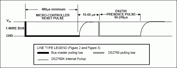
Figure 1. 1-Wire Reset and Presence Pulse.
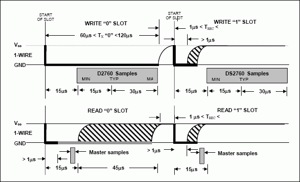
Figure 2. 1-Wire Write and Read Time Slot.
Software control
In order to accurately control the timing requirements the 1-Wire interface, certain key functions must first be established. The first function created must be the "delay" function which is integral to all read and write control. This function will be entirely dependent the speed of the microcontroller. For this example, a DS5000 (8051-compatible) microcontroller running at 11.059MHz was used. The example below illustrates the C prototype function for creating the timing delay. Calling this routine takes 24µs and then each count takes another 16µs.// DELAY - with an 11.059MHz crystal.
// Calling the routine takes about 24µs, and then each count takes another 16µs.
void delay(int µseconds)
{
int s;
for (s=0; s<µseconds;s++);
}
The reset time slot is 480µs and is described in C below. The DQ line is pulled low and held low for a delay of "29" which is actually a 488µs delay. The DQ line is then released to a high state. After a delay of "3", which is 72µs, the master samples the DQ line to see if a device has responded by pulling the DQ line low to indicate the device "presence."// OW_RESET - performs a reset on the one-wire bus and returns the presence detect.
// Reset is 480µs, so delay value is (480-24)/16 = 28.5 - we use 29.
// Presence checked another 70µs later, so delay is (70-24)/16 = 2.875 - we use 3.
//
unsigned char ow_reset(void)
{
unsigned char presence;
DQ = 0; //pull DQ line low
delay(29); // leave it low for 480µs
DQ = 1; // allow line to return high
delay(3); // wait for presence
presence = DQ; // get presence signal
delay(25); // wait for end of timeslot
return(presence); // presence signal returned
} // 0=presence, 1 = no part
Each bit that is read follows a similar sequence as the 1-Wire Reset, but without the delays. The DQ line is pulled low and then released and then the master samples the DQ line and then returns the value.//////////////////////////////////////////////////////////////////////////////
// READ_BIT - reads a bit from the one-wire bus. The delay
// required for a read is 15µs, so the DELAY routine won't work.
// We put our own delay function in this routine in the form of a
// for() loop.
//
unsigned char read_bit(void)
{
unsigned char i;
DQ = 0; // pull DQ low to start timeslot
DQ = 1; // then return high
for (i=0; i<3; i++); // delay 15µs from start of timeslot
return(DQ); // return value of DQ line
}
When a bit is written, the master pulls the line low for 1µs for a write "1" or 104µs, in this case, for a write "0".//////////////////////////////////////////////////////////////////////////////
// WRITE_BIT - writes a bit to the one-wire bus, passed in bitval.
void write_bit(char bitval)
{
DQ = 0; // pull DQ low to start timeslot
if(bitval==1) DQ =1; // return DQ high if write 1
delay(5); // hold value for remainder of timeslot
DQ = 1;
}// Delay provides 16µs per loop, plus 24µs. Therefore delay(5) = 104µs
Reading and writing a byte is simply reading or writing 8 bits one after another starting with the least significant bit.//////////////////////////////////////////////////////////////////////////////
// READ_BYTE - reads a byte from the one-wire bus.
//
unsigned char read_byte(void)
{
unsigned char i;
unsigned char value = 0;
for (i=0;i<8;i++)
{
if(read_bit()) value|=0x01<<i; // reads byte in, one bit at a time and then
// shifts it left
delay(6); // wait for rest of timeslot
}
return(value);
}
//////////////////////////////////////////////////////////////////////////////
// WRITE_BYTE - writes a byte to the one-wire bus.
//
void write_byte(char val)
{
unsigned char i;
unsigned char temp;
for (i=0; i<8; i++) // writes byte, one bit at a time
{
temp = val>>i; // shifts val right 'i' spaces
temp &= 0x01; // copy that bit to temp
write_bit(temp); // write bit in temp into
}
delay(5);
}
Reading the net Address
Every DS2760 has a unique 64 bit Net Address. The Read Net Address command is used to find the 64- bit Net Address when only a single device is on the 1-Wire bus. Multiple devices require the use of the Search Net Address functions not shown here. The DS2760 can be configured to use the Read Net Address of 0x33h or 0x39h.unsigned char Read_NetAddress(void)
{
int n;
char dat[9];
if(ow_reset()==0) //If a presence is detected, continue to read
{
write_byte(0x33); //Read Net Address Command (0x33h)
for (n=0;n<8;n++)
dat[n]=read_byte(); //Read 8 bytes of Net Address
printf("\n Net Address Code %X%X%X%X\n",dat[7],dat[6],dat[5],dat[4],dat[3],dat[2],dat[1],dat[0]);
return(0); //Return 0 if no error
}
return(1); //Return 1 if no presence detected
}
Reading Real Time Data
If there is a single device on the 1 Wire bus, then the real time readings of voltage, current, accumulated current and temperature can be used directly as shown below. If more than 1 device is present, a Match Net Address routine must be used. All of these functions could be combined into a single routine by simply starting with the Voltage Register Address and then continuing to issue the read_byte() command until all desired bytes are read.unsigned char Read_ Voltage (void)
{
int lsb, msb, temp;
float Voltage; //This value may be declared globally
if(ow_reset()==0) //If a presence is detected, continue to read
{
write_byte(0xCC); // Skip Net Address Command
write_byte(0x69); // Read Registers Command
write_byte(0x0C); // Voltage Register Address
msb = read_byte(); // Read msb
lsb = read_byte() & 0xE0; // Read lsb and mask off lower 5 bits
if((msb & 0x80) == 0x80) //if sign bit is set
temp = (msb<<8 + lsb) - 65536;
else
temp = msb<<8 + lsb;
Voltage = (temp>>5) * 0.00488; //Voltage in Volts
printf("\nVoltage = &d", Voltage);
return(0); //Return 0 if no error
}
return(1); //Return 1 if no presence detected
}
unsigned char Read_NetAddress(void)
{
int n;
char dat[9];
if(ow_reset()==0) //If a presence is detected, continue to read
{
write_byte(0x33); //Read Net Address Command (0x33h)
for (n=0;n<8;n++)
dat[n]=read_byte(); //Read 8 bytes of Net Address
printf("\n Net Address Code %X%X%X%X\n",dat[7],dat[6],dat[5],dat[4],dat[3],dat[2],dat[1],dat[0]);
return(0); //Return 0 if no error
}
return(1); //Return 1 if no presence detected
}
unsigned char Read_Current (void)
{
int lsb, msb, temp;
float Current; //This value may be declared globally
if(ow_reset()==0) //If a presence is detected, continue to read
{
write_byte(0xCC); // Skip Net Address Command
write_byte(0x69); // Read Registers Command
write_byte(0x0E); //Current Register Address
msb = read_byte(); // Read msb
lsb = read_byte() & 0xF8; // Read lsb and mask off lower 3 bits
if((msb & 0x80) == 0x80) //if sign bit is set
temp = (msb<<8 + lsb) - 65536;
else
temp = msb<<8 + lsb;
Current = (temp>>3) * 0.000015625 / .025; //Current in mAmps
//assuming a 25mOhm Sense Resistor
printf("\nCurrent = &d", Current);
return(0); //Return 0 if no error
}
return(1); //Return 1 if no presence detected
}
unsigned char Read_ACR(void)
{
int lsb, msb, temp;
float ACR; //This value may be declared globally
if(ow_reset()==0) //If a presence is detected, continue to read
{
write_byte(0xCC); // Skip Net Address Command
write_byte(0x69); // Read Registers Command
write_byte(0x10); //ACR Register Address
msb = read_byte(); // Read msb
lsb = read_byte(); // Read lsb
if((msb & 0x80) == 0x80) //if sign bit is set
temp = (msb<<8 + lsb) - 65536;
else
temp = msb<<8 + lsb;
ACR = temp * 0.00625 / .025; //Capacity in mAhrs
//assuming a 25mOhm Sense Resistor
printf("\nACR = &d", ACR);
return(0); //Return 0 if no error
}
return(1); //Return 1 if no presence detected
}
unsigned char Read_Temperature(void)
{
int lsb, msb,temp;
float temp_f,temp_c; //These values may be declared globally
if(ow_reset()==0) //If a presence is detected, continue to read
{
write_byte(0xCC); // Skip Net Address Command
write_byte(0x69); // Read Registers Command
write_byte(0x18); //Temperature Register Address
msb = read_byte(); // Read msb
lsb = (read_byte() & 0xE0); // Read lsb, mask off lower 5 bits
if((msb & 0x80) == 0x80) //if sign bit is set
temp = (msb<<8 + lsb) - 65536;
else
temp = msb<<8 + lsb;
temp_c = (temp>>5) * 0.125; //temperature in Degrees C
temp_f = ((temp_c)* 9)/5 + 32; //temperature in Degrees F
printf("\nTemp C = &d", temp_c);
printf("\nTemp F = &d", temp_f);
return(0); //Return 0 if no error
}
return(1); //Return 1 if no presence detected
}
unsigned char Read_UserMemory(void)
{
int j;
int Memory[32]; //This value may be declared globally
if(ow_reset()==0) //If a presence is detected, continue to read
{
write_byte(0xCC); // Skip Net Address Command
write_byte(0x69); // Read Registers Command
write_byte(0x20); // Block 0 Address
for (j=0;j<32;j++) //Read all 32 Bytes
{
Memory[j]=read_byte();
printf("\n%X , " , Memory[j]);
}
return(0); //Return 0 if no error
}
return(1); //Return 1 if no presence detected
}
Reading User Memory
The DS2760 contains 32 bytes of user EEPROM that can be read using the following code.unsigned char Read_UserMemory(void)
{
int j;
int Memory[32]; //This value may be declared globally
if(ow_reset()==0) //If a presence is detected, continue to read
{
write_byte(0xCC); // Skip Net Address Command
write_byte(0x69); // Read Registers Command
write_byte(0x20); // Block 0 Address
for (j=0;j<32;j++) //Read all 32 Bytes
{
Memory[j]=read_byte();
printf("\n%X , " , Memory[j]);
}
return(0); //Return 0 if no error
}
return(1); //Return 1 if no presence detected
}
Appendix A
DS5000 (8051 SOURCE CODE)
// ds2760k.c -- Functions for the Dallas Semiconductor DS2760K
// Li-Ion Battery Monitor 1-Wire Kit Module
// Designed for 8051 microcontrollers
// This code was developed using the DS5000/DS2250-64-16
// and the Keil version 6.1 DS5000T source code Compiler
//----------------------------------------------------------------------
//#pragma CODE SMALL OPTIMIZE(3)
// command line directives
#include <absacc.h> // absolute addressing modes
#include <ctype.h> // character types
#include <math.h> // standard math
#include <stdio.h> // standard I/O
#include <string.h> // string functions
#include "ds50001w.h" // DS5000 series 8052 registers
// Configuration parameters
#define XtalFreq (11059490) // main crystal frequency
#define CntrFreq (XtalFreq/12) // main counter frequency
#define BaudRate (9600) // baud rate
#define CntrTime (8) // number of cycles for counter
#define Ft (32768.0) // target crystal frequency
//////////////////////////////////////////////////////////////////////////////
// DELAY - with an 11.059MHz crystal.
// Calling the routine takes about 24µs, and then
// each count takes another 16µs.
//
void delay(int µseconds)
{
int s;
for (s=0; s<µseconds;s++);
}
//////////////////////////////////////////////////////////////////////////////
// OW_RESET - performs a reset on the one-wire bus and
// returns the presence detect. Reset is 480µs, so delay
// value is (480-24)/16 = 28.5 - we use 29. Presence checked
// another 70µs later, so delay is (70-24)/16 = 2.875 - we use 3.
//
unsigned char ow_reset(void)
{
unsigned char presence;
DQ = 0; //pull DQ line low
delay(29); // leave it low for 480µs
DQ = 1; // allow line to return high
delay(3); // wait for presence
presence = DQ; // get presence signal
delay(25); // wait for end of timeslot
return(presence); // presence signal returned
} // 0=presence, 1 = no part
//////////////////////////////////////////////////////////////////////////////
// READ_BIT - reads a bit from the one-wire bus. The delay
// required for a read is 15µs, so the DELAY routine won't work.
// We put our own delay function in this routine in the form of a
// for() loop.
unsigned char read_bit(void)
{
unsigned char i;
DQ = 0; // pull DQ low to start timeslot
DQ = 1; // then return high
for (i=0; i<3; i++); // delay 15µs from start of timeslot
return(DQ); // return value of DQ line
}
//////////////////////////////////////////////////////////////////////////////
// WRITE_BIT - writes a bit to the one-wire bus, passed in bitval.
//
void write_bit(char bitval)
{
DQ = 0; // pull DQ low to start timeslot
if(bitval==1) DQ =1; // return DQ high if write 1
delay(5); // hold value for remainder of timeslot
DQ = 1;
}// Delay provides 16µs per loop, plus 24µs. Therefore delay(5) = 104µs
//////////////////////////////////////////////////////////////////////////////
// READ_BYTE - reads a byte from the one-wire bus.
//
unsigned char read_byte(void)
{
unsigned char i;
unsigned char value = 0;
for (i=0;i<8;i++)
{
if(read_bit()) value|=0x01<<i; // reads byte in, one bit at a time and then
// shifts it left
delay(6); // wait for rest of timeslot
}
return(value);
}
//////////////////////////////////////////////////////////////////////////////
// WRITE_BYTE - writes a byte to the one-wire bus.
//
void write_byte(char val)
{
unsigned char i;
unsigned char temp;
for (i=0; i<8; i++) // writes byte, one bit at a time
{
temp = val>>i; // shifts val right 'i' spaces
temp &= 0x01; // copy that bit to temp
write_bit(temp); // write bit in temp into
}
delay(5);
}
//////////////////////////PROTOTYPE FUNCTIONS////////////////////////////
unsigned char Read_NetAddress(void);
unsigned char Read_Temperature(void);
unsigned char Read_Current(void);
unsigned char Read_Voltage(void);
unsigned char Read_ACR(void);
unsigned char Read_UserMemory(void);
/////////////////////////BEGIN MAIN PROGRAM//////////////////////////////
main()
{
unsigned char Select_Type; // Function variable
// Inhibit the watchdog timer and set up memory
TA = 0xAA; // timed access
TA = 0x55;
PCON = 0x00; // inhibit watchdog timer
// Set up the serial port
SCON = 0x50; // SCON: mode 1, 8-bit UART, enable rcvr
TMOD = 0x21; // TMOD: timer 1, mode 2, 8-bit reload
// TMOD: timer 0, mode 1, 16-bit
PCON |= 0x80; // SMOD = 1 Double Baud Rate for TH1 load
TH0=TL0 = 0;
TH1=TL0 = (unsigned int)(256 - ( (XtalFreq / BaudRate) / 192));
TR0 = 1; // TR0: timer 0 run
TR1 = 1; // TR1: timer 1 run
TI = 1; // TI: set TI to send first char of UART
//----------------------------------------------------------------------
// Display DS2760 1-Wire Device banner
//----------------------------------------------------------------------
printf ("\n");
printf (" Dallas Semiconductor – Battery Management\n");
printf (" Source for DS2760K Li-Ion Battery Monitor \n");
printf (" Updated Code September 3, 2002 \n");
printf (" [C Program for DS500x/DS2250 or 8051 Compatible Microcontroller]");
printf("\n\n");
printf("\n********************************************************************\n");
printf (" Select Menu Option\n");
printf (" 1. One-Wire Reset\n");
printf (" 2. Read Net Address of Single Device\n");
printf (" 3. Read Temperature\n");
printf (" 4. Read Current\n");
printf (" 5. Read Current Accumulator (ACR)\n");
printf (" 7. Read Voltage\n");
printf (" 7. Read User Memory\n");
printf ("\n\n");
printf (" Note: This program represents an example only.\n");
printf (" No warranties or technical support is provided with this program.\n");
do {
// Enable CE2
EA = 0; // Inhibit interrupts
TA = 0xAA; // timed access
TA = 0x55;
MCON = MCON |= 0x04; // Enable topside CE 0xCC
// Disable CE2
TA = 0xAA; // timed access
TA = 0x55;
MCON = 0xC8; // Disable topside CE
EA = 1; // Enable interrupts
Select_Type = getchar(); // get variable to start
switch(Select_Type)
{
case '1': printf ("\n 1. Sent 1-Wire Reset\n");
if(ow_reset()==0);
printf ("\n Presence Detected");
else
printf ("\n No Presence Detected");
break;
case '2': printf (" 2. Read Net Address of Single Device\n");
if (Read_NetAddress()<>0);
printf ("\n Error Reading DS2760");
break;
case '3': printf ("\n 5. Read Temperature\n");
if (Read_Temperature()<>0);
printf ("\n Error Reading DS2760");
break;
case '4': printf ("\n 6. Read Current\n");
if (Read_Current ()<>0);
printf ("\n Error Reading DS2760");Read_Current();
break;
case '5': printf ("\n 7. Read Current Accumulator (ACR)\n");
if (Read_ACR ()<>0);
printf ("\n Error Reading DS2760");Read_Current();
break;
case '6': printf ("\n 8. Read Voltage\n");
if (Read_Voltage ()<>0);
printf ("\n Error Reading DS2760");Read_Current();
break;
case '7': printf ("\n 8. Read User Memory\n");
if (Read_UserMemory ()<>0);
printf ("\n Error Reading DS2760");Read_Current();
break;
default: printf ("\n Typ Select Another Menu Option\n");
break;
}; // end switch
} while (1); // Loop forever
}
Appendix B
DS5000 (8051 C INCLUDE HEADER FILE)
/*-----------------------------------------------------------------------------
DS5000.H
Header file for Dallas Semiconductor DS5000.
Copyright (c) 1995-1996 Keil Software, Inc. All rights reserved.
-----------------------------------------------------------------------------*/
#ifndef DS5000_HEADER_FILE
#define DS5000_HEADER_FILE 1
/*------------------------------------------------
DS5000 Byte Registers
------------------------------------------------*/
sfr P0 = 0x80;
sfr SP = 0x81;
sfr DPL = 0x82;
sfr DPH = 0x83;
sfr PCON = 0x87;
sfr TCON = 0x88;
sfr TMOD = 0x89;
sfr TL0 = 0x8A;
sfr TL1 = 0x8B;
sfr TH0 = 0x8C;
sfr TH1 = 0x8D;
sfr P1 = 0x90;
sfr SCON = 0x98;
sfr SBUF = 0x99;
sfr P2 = 0xA0;
sfr IE = 0xA8;
sfr P3 = 0xB0;
sfr IP = 0xB8;
sfr MCON = 0xC6;
sfr TA = 0xC7;
sfr PSW = 0xD0;
sfr ACC = 0xE0;
sfr B = 0xF0;
/*------------------------------------------------
DS5000 P0 Bit Registers
------------------------------------------------*/
//sbit P0_0 = 0x80; // Set Output Here
sbit DQ = 0x80; // Set Output Here
sbit P0_1 = 0x81;
sbit P0_2 = 0x82;
sbit P0_3 = 0x83;
sbit P0_4 = 0x84;
sbit P0_5 = 0x85;
sbit P0_6 = 0x86;
sbit P0_7 = 0x87;
/*------------------------------------------------
DS5000 PCON Bit Values
------------------------------------------------*/
#define IDL_ 0x01
#define STOP_ 0x02
#define EWT_ 0x04
#define EPFW_ 0x08
#define WTR_ 0x10
#define PFW_ 0x20
#define POR_ 0x40
#define SMOD_ 0x80
/*------------------------------------------------
DS5000 TCON Bit Registers
------------------------------------------------*/
sbit IT0 = 0x88;
sbit IE0 = 0x89;
sbit IT1 = 0x8A;
sbit IE1 = 0x8B;
sbit TR0 = 0x8C;
sbit TF0 = 0x8D;
sbit TR1 = 0x8E;
sbit TF1 = 0x8F;
/*------------------------------------------------
DS5000 TMOD Bit Values
------------------------------------------------*/
#define T0_M0_ 0x01
#define T0_M1_ 0x02
#define T0_CT_ 0x04
#define T0_GATE_ 0x08
#define T1_M0_ 0x10
#define T1_M1_ 0x20
#define T1_CT_ 0x40
#define T1_GATE_ 0x80
#define T1_MASK_ 0xF0
#define T0_MASK_ 0x0F
/*------------------------------------------------
DS5000 P1 Bit Registers
------------------------------------------------*/
sbit P1_0 = 0x90;
sbit P1_1 = 0x91;
sbit P1_2 = 0x92;
sbit P1_3 = 0x93;
sbit P1_4 = 0x94;
sbit P1_5 = 0x95;
sbit P1_6 = 0x96;
sbit P1_7 = 0x97;
/*------------------------------------------------
DS5000 SCON Bit Registers
------------------------------------------------*/
sbit RI = 0x98;
sbit TI = 0x99;
sbit RB8 = 0x9A;
sbit TB8 = 0x9B;
sbit REN = 0x9C;
sbit SM2 = 0x9D;
sbit SM1 = 0x9E;
sbit SM0 = 0x9F;
/*------------------------------------------------
DS5000 P2 Bit Registers
------------------------------------------------*/
sbit P2_0 = 0xA0;
sbit P2_1 = 0xA1;
sbit P2_2 = 0xA2;
sbit P2_3 = 0xA3;
sbit P2_4 = 0xA4;
sbit P2_5 = 0xA5;
sbit P2_6 = 0xA6;
sbit P2_7 = 0xA7;
/*------------------------------------------------
DS5000 IE Bit Registers
------------------------------------------------*/
sbit EX0 = 0xA8;
sbit ET0 = 0xA9;
sbit EX1 = 0xAA;
sbit ET1 = 0xAB;
sbit ES = 0xAC;
sbit EA = 0xAF;
/*------------------------------------------------
DS5000 P3 Bit Registers (Mnemonics & Ports)
------------------------------------------------*/
sbit RD = 0xB7;
sbit WR = 0xB6;
sbit T1 = 0xB5;
sbit T0 = 0xB4;
sbit INT1 = 0xB3;
sbit INT0 = 0xB2;
sbit TXD = 0xB1;
sbit RXD = 0xB0;
sbit P3_0 = 0xB0;
sbit P3_1 = 0xB1;
sbit P3_2 = 0xB2;
sbit P3_3 = 0xB3;
sbit P3_4 = 0xB4;
sbit P3_5 = 0xB5;
sbit P3_6 = 0xB6;
sbit P3_7 = 0xB7;
/*------------------------------------------------
DS5000 IP Bit Registers
------------------------------------------------*/
sbit PX0 = 0xB8;
sbit PT0 = 0xB9;
sbit PX1 = 0xBA;
sbit PT1 = 0xBB;
sbit PS = 0xBC;
sbit RWT = 0xBF;
/*------------------------------------------------
DS5000 MCON Bit Values
------------------------------------------------*/
#define SL_ 0x01
#define PAA_ 0x02
#define ECE2_ 0x04
#define RA32_8_0x08
#define PA0_ 0x10
#define PA1_ 0x20
#define PA2_ 0x40
#define PA3_ 0x80
/*------------------------------------------------
DS5000 PSW Bit Registers
------------------------------------------------*/
sbit P = 0xD0;
sbit OV = 0xD2;
sbit RS0 = 0xD3;
sbit RS1 = 0xD4;
sbit F0 = 0xD5;
sbit AC = 0xD6;
sbit CY = 0xD7;
/*------------------------------------------------
Interrupt Vectors:
Interrupt Address = (Number * 8) + 3
------------------------------------------------*/
#define IE0_VECTOR 0 /* 0x03 */
#define TF0_VECTOR 1 /* 0x0B */
#define IE1_VECTOR 2 /* 0x13 */
#define TF1_VECTOR 3 /* 0x1B */
#define SIO_VECTOR 4 /* 0x23 */
#define PFW_VECTOR 5 /* 0x2B */
/*------------------------------------------------
------------------------------------------------*/
#endif