Manchester Data Encoding for Radio CommunicaTIons
Abstract: Manchester encoding has gained wide acceptance as the modulaTIon scheme for low-cost radio-frequency transmission of digital data. This form of binary phase-shift keying is a simple method for encoding digital serial data of arbitrary bit patterns without any long strings of conTInuous zeros or ones, and having the encoding clock rate embedded within the transmitted data.
Manchester encoding is a form of binary phase-shift keying (BPSK) that has gained wide acceptance as the modulaTIon scheme for low-cost radio-frequency (RF) transmission of digital data. Manchester is a simple method for encoding digital serial data of arbitrary bit patterns without having any long strings of continuous zeros or ones, and having the encoding clock rate embedded within the transmitted data. These two characteristics enable low-cost data-recovery circuits to be constructed that can decode transmitted data with variable signal strengths from transmitters with imprecise, low-cost, data-rate clocks.
The encoding of digital data in Manchester format defines the binary states of "1" and "0" to be transitions rather than static values. There are two possible definitions (as shown in Figures 1 and 2) that have alternate assignments of the logic levels to the two possible transitions of rising and falling edges.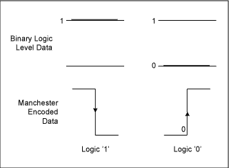
Figure 1. Defining logical binary data as edge transitions.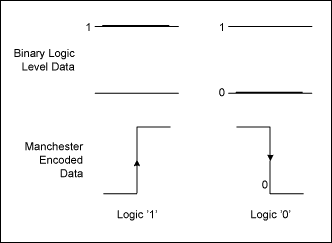
Figure 2. Equally valid alternate definitions of binary data as edge transitions.
The definition of a bit in Manchester-encoded data can become confusing, because each binary data bit encoded results in two apparent "bits" in the encoded data stream. Keeping in mind that an encoded data bit is defined as a transition, it easy to see that there are no bits in Manchester data streams. The Manchester-encoded data stream does require two levels for each transition, because by definition the information is encoded as a low-level to high-level transition or high-level to low-level transition. Thus, it takes twice as many logic-level states to encode data in Manchester. However, the use of the phrase "Manchester bits" persists and care should be taken when using the term "bit" to specify whether it is a serial data bit or a Manchester-encoded bit. The term chip is often used to describe the level periods on either side of a transition or edge. Thus, each Manchester data encoding of a logic level bit requires two chips. A sample serial data stream is shown in Figure 3.
Figure 3. Manchester encoding of a serial data stream using the definition shown in Figure 1.
A key benefit of Manchester encoding is that, on average, the DC component level of the encoded data stream is zero. Regardless of the peak-to-peak amplitude of the encoded data stream, the transitions can always be identified as the point where the encoded data stream transitions across the median level (zero, in this example). Low-cost data-decoders use this characteristic in a simple transition-detector circuit called a data-slicer. A simple implementation of a data-slicer is shown in Figure 4, using a simple comparator to decode, or slice, the encoded data stream. A low-pass filter comprised of R1 and C1 track the DC average of the incoming serial data stream with a time constant chosen to be much longer than the serial data chip rate. The averaged voltage on C1 establishes the negative input reference value for the comparator. The serial data stream is also presented to the positive input of the comparator so that the transitions above and below the average values cause the comparator output to swing between the upper and lower supply voltages.
Figure 5 shows an example of a Manchester-encoded serial-input data stream and the resulting output data stream. Note that in this example, the encoded data stream has a DC offset from the zero level, as is typical in RF receivers. The data-slicer effectively converts the incoming data stream into a binary serial stream that swings between power supply rails, as is typical in digital systems. This binary level restoration makes the encoded serial data stream suitable for further decoding and processing with standard digital circuits.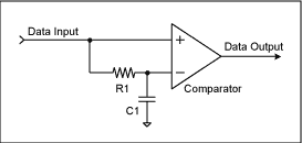
Figure 4. A simple data-slicer circuit for restoring binary logic levels.
The example circuit shown in Figure 5 also includes resistors R2 and R3 that form a positive feedback for added hysteresis in the comparator circuit. The hysteresis reduces multiple edges that occur with slow-changing or noisy input signals.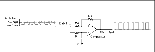
Figure 5. Low-level Manchester data stream input is data-sliced to a logic level output.
Once the Manchester-encoded data has been data-sliced into a serial data stream with restored logic-level voltages, a data-decoder is used to extract the original serial data information that was encoded. Typically, the data-decoder is a simple microcontroller running a software algorithm that identifies the binary transitions between logic levels to assign a binary "1" or "0" value to the data. In a given system, the microcontroller software can anticipate the timing of the logic-level transitions, knowing the approximate baud rate of the encoded data. This utilizes the second benefit of Manchester-encoded data—the embedded baud-rate clock. In situations where the received data stream is close to the noise floor (low RF-signal levels from distant transmitters, for example) the transition edges might have multiple transitions on the data-slicer output. A microcontroller software algorithm can be written to not only anticipate the timing of valid edges but which can reject further edges that occur until the next valid edge transition time. Although hardware implementations of data-decoders can be realized, the complexity of the circuit often is not cost-competitive with a simple microcontroller. Further, the microcontroller can perform other functions such as activating digital outputs when certain data is received, such as unlocking a car door when the proper identification key and control function are decoded. 
Figure 6. Basic components of a typical RF Manchester data receiver system.
Manchester data encoding is typically described as the process of a logical combining of the serial data to be encoded and the clock used to establish the bit rate. An example of such a circuit is shown in Figure 7. One use of a circuit like this could be to encode the serial data from a microcontroller UART output. The circuit shown omits required functions that prevent multiple edge generation during the transition of the clock and data inputs as they transition through intermediate logic-level states.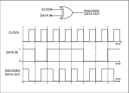
Figure 7. Manchester encoding by combining data-rate clock and serial data by XOR.
However, the XOR definition for encoding the data does not immediately convey the simplicity of creating the Manchester-encoded data stream using a microcontroller as the transmitter encoder shown in Figure 8, and using software to do the encoding and serial data-rate timing. In this way, it is not necessary to use a microcontroller with hardware UART and external circuits for transmitting Manchester-encoded data. An internal timer on the microcontroller triggers a subroutine to update the output pin according to the data being transmitted, and thus establishes the data-rate time. The time base of the microcontroller does not have to be precise, as the encoded data contains all of the information regarding the data and clock embedded within to be used by the decoding receiver.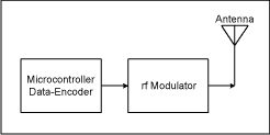
Figure 8. A microcontroller can create Manchester encoding using software.