IntroducTIon
As IC designers strive to put more transistors running at higher speeds into smaller packages, there can be only one outcome: heat! Couple this with the fact that these high-power ICs are being designed into ever-shrinking boxes, and you end up with a real thermal management problem. For many applications, this means using fans. Unfortunately with fan use comes the usual fan headaches of mechanical failures, increased power consumption, and more noise. Fan speed control and monitoring can ease some of these headaches, resulting in quieter, more reliable fans that use less power.Brushless DC Fans
Before we get into the subject of regulating and monitoring fans, we first need to understand the fans themselves. Brushless DC fans tend to be the solution of choice for most electronic enclosures. These fans couple high reliability with ease of use. The basic DC brushless fan is a 2-wire device over which a DC voltage is applied. That's all it takes. The simplest approach to system cooling is to connect a fan to a DC power supply and let it run. A quick glance at fan catalogs reveals that fans operating at a nominal 5V, 12V, 24V, or 48V are available. At the present time, 12V fans seem to be the most popular. As more and more systems are designed without a 12V power supply, 5V fans will probably become more prevalent. In telecom applications, 48V fans are especially popular.Brushless DC fans are called "brushless" because the electric motor within the fan is commutated electronically. Older DC fans used mechanical brushes, which spewed particles and EMI throughout the system, and over time would wear and eventually fail. Brushless fans have replaced these mechanical brushes with electronic sensors and switches that now perform the necessary commutation. This commutation circuitry is mounted within the fan itself and is totally transparent to the user. The end result is a simple-to-use, reliable, 2-wire device. This has greatly increased the lifetime and the reliability of these fans.
To the end user, DC brushless fans are fairly simple to characterize electrically. As the DC voltage applied to the fan is varied, its speed and current draw also vary. To a first order, speed and current are directly proportional to the DC voltage applied. See Figures 1 and 2.
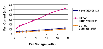
Figure 1. Fan current versus fan voltage (12V-rated fans).
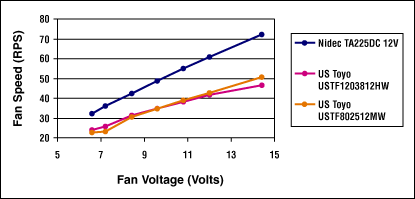
Figure 2. Fan speed versus fan voltage (12V-rated fans).
Fan-Monitoring Options
Although brushless commutation has gone a long way in increasing the lifetime and the reliability of fans, they are still mechanical devices and prone to mechanical wear and failure. Over time, fan speed and therefore cooling efficiency can slowly degrade or fail completely. This is why it can be important to continuously monitor the condition of the fan. Most fan manufactures offer a variety of ways to do this. These options fall into roughly two categories: alarm sensors and speed sensors. Alarm sensors typically give a digital signal indicating that the fan has fallen below some threshold of speed or has stopped altogether. As one example, EBM/Papst offers an option that generates a series of low-going digital pulses whenever the speed of the fan drops to 75%-85% of its nominal speed. NMB Technologies offers a slightly different option that they call a "Locked Rotor Alarm Signal." This signal goes high whenever the fan stops spinning completely.Both EBM/Papst and NMB, along with other manufactures, offer fans with speed sensors that give a digital output whose frequency is proportional to the fan speed. The most common speed sensor gives two pulses per revolution. Depending on the manufacturer and the options offered, both speed and alarm sensors can be ordered with either open-collector or internally pulled-up outputs. Internally pulled-up outputs can be TTL-compatible or can swing the full supply voltage of the fan. Figure 3 shows the output stages available from EBM/Papst. It's important to note that the alarm and speed sensors share the same supply voltage as the motor and its commutation electronics. Any changes in supply voltage to control the speed of the fan will also affect the commutation electronics and the speed/alarm sensors.
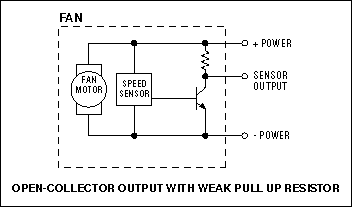
Figure 3a. This speed-sensor output is an open-collector with a weak pullup resistor, and not necessarily TTL-compatible.
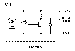
Figure 3b. The zener diode connected to this speed-sensor output ensures TTL compatibility.
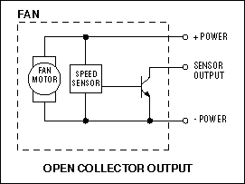
Figure 3c. This open-collector speed-sensor output allows maximum flexibility at the minor expense of an external pullup resistor.
Why Use Speed Control?
When a fan is selected for an application, it must be designed for worst-case conditions. This means selecting a fan that can move enough air to keep the system sufficiently cool even with worst-case ambient temperature, power dissipation, fan production tolerances, and fan aging. The reality of the situation is that the system will spend most of its time well under worst-case conditions. At this point, it should be obvious that under most conditions fan speed can be reduced without adverse effects on the system and increased only when conditions demand it. Not so obvious would be the question, why bother then with fan speed control?Reduced Audible Noise
One of the most immediately noticeable advantages of fan speed control comes in the form of relief for your ears. Fans running at full speed can be a significant source of annoyance, especially for equipment used in quiet office environments. Most office environments are usually at a temperature significantly less than electronic equipment is designed to operate up to, which means fan speed can be reduced without adverse effects, much to the relief of everyone within hearing distance.Reduced Power Consumption
Applications such as laptops will benefit from reduced power consumption. Figure 4 shows typical power consumption versus fan speed for three different fans. Power consumption can be approximated as a square of the fan's speed. In the case of the Nidec fan in Figure 4, reducing the fan speed to 69% of its nominal at 12V cuts power consumption in half.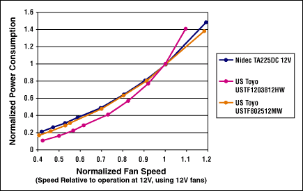
Figure 4. Power consumption versus fan speed.
Increased Lifetime
Reducing fan speed also decreases the wear on the fan. Fan wear is a rough function of the absolute number of revolutions of the fan. Reduced wear translates into increased lifetimes and therefore greater MTBFs. Because fans are mechanical, they tend to be one of the more common failures in a system. Anything that can be done to improve the MTBF for a fan will also cause a significant increase (in MTBF) in the end equipment. This can be especially important in systems such as servers and networking equipment.Reduced Clogging
As anyone who has opened up old equipment knows, dust seems to be attracted to electronics, especially in systems with fans. As dust collects at the inlet and the exhausts of systems with fans, airflow can diminish or be stopped altogether. This, of course, can result in decreased cooling and higher temperatures. Reduced fan speed can lessen the rate at which systems collect this dust, thus extending the systems' life.Methods of Speed Control
Now that we better understand DC brushless fans, their available options, and the benefits of speed control, let's look at three methods of controlling speed. Each method offers a trade-off when it comes to cost versus performance.PWMing the Fan Directly
Pulse-width modulating (PWMing) the fan directly involves turning the fan's power supply on and off at a fixed frequency. Duty-cycle adjustments are made to control the speed of the fan. The larger the duty cycle, the faster the fan spins. Choosing the appropriate frequency for this method can be somewhat tricky. If the frequency of the PWM signal is too slow, the fan's speed will noticeably oscillate within a PWM cycle. To illustrate this point, take the ridiculous extreme of a 50% duty-cycle, .01Hz drive signal. The fan will spin to full speed during the first 50 seconds and then stop within the next 50 seconds. The frequency can also be too high, as commutation is done electronically using circuits that are powered off the fan's plus and minus terminals. PWMing the fan and therefore the internal commutation electronics too quickly can cause the internal commutation electronics to cease functioning correctly. Remember that these electronics were not designed to run on anything but DC supplies. Thus, useful frequencies range from 20Hz to 160Hz. In addition, the PWM rise and fall times must be sufficiently slow to ensure long-term reliability of the fan.As with all things, PWMing has its advantages and disadvantages. The advantages include a very simple drive circuit (see Figures 8a and 8b), good startup characteristics, and minimal heat dissipation in the pass transistor. The disadvantages involve increased stress on the fan and the inability to use speed or alarm sensors. Remember that speed and alarm sensors are powered off the same supply voltage as the motor. Because the supply voltage is being powered on and off at a 20Hz to 160Hz rate, the speed and alarm circuitry is also being powered up and down, effectively rendering the speed and alarm sensors useless.
During PWM control, the voltage applied to the fan is either its rated voltage (12V in the case of a 12V fan) or zero volts. However, because the fan is spinning at something less than its rated speed (remember, that's the whole idea), its back EMF is reduced. This causes higher-than-nominal current flow through the windings during the on period of the PWM cycle. Although fans are designed to handle increased currents, such as during startup, heightened currents at 30 times per second for the life of the fan can entail negative reliability issues. But even with these negatives, PWM control can be the appropriate solution in low-cost noncritical applications.
Linear Regulation
As the term implies, "linear regulation" adjusts the DC voltage across the fan by using a linear regulator. When using this method, it is important to make sure the fan is specified to operate over a wide range of voltages. EBM/Papst, for example, has fans that are specified from 50% to 125% of their nominal voltage. One major advantage linear regulation has over PWMing is that it allows the use of speed and alarm sensors. Unfortunately, linear regulation also has its drawbacks: mainly power dissipation in the pass element, as well as startup and stalling issues.Linear regulators work by controlling the DC voltage across the fan. They do this by dissipating power in the form of heat. It probably seems silly to generate heat in order to cool something down. But it's not as ridiculous as you might think. During maximum and minimum cooling, power dissipation will ideally be zero. During maximum cooling, the pass element is fully on, so the voltage across it is nearly zero. Zero volts means zero power dissipation. During minimum cooling, the pass element is off (zero current flows), so again power dissipation is zero. As mentioned earlier, the current draw of the fan can be approximated as a linear function of the voltage applied, making it look resistive. With this in mind, worst-case power dissipation occurs roughly when the voltage across the fan is 1/2 its maximum operating voltage. See Figure 5. This means worst-case power dissipation in the pass element can be estimated by the following equation: P = 1/4(Vmax x Imax), where Imax and Vmax are the rated voltages and currents of the fan, respectively. For example, a 1.2-watt fan (12V at 98mA) will have worst-case power dissipation across the pass element of only 300mW when run at 6V with a 12V supply. It is comforting to note that maximum heat dissipation in the fan circuit occurs during minimal cooling requirements. Also, even though a power-dissipating device is being used, there is still an overall power savings when fan speed is reduced. See Figure 6.
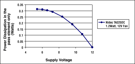
Figure 5. Power dissipation in a linear-regulator pass element versus fan voltage.
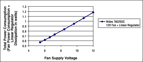
Figure 6. Total power consumption of a linearly regulated fan circuit.
Startup and stall issues are related. Fans require a certain voltage before they will start. This is called "startup voltage." Once a fan is already spinning, decreasing the voltage below the stall voltage will cause the fan to stop. The startup voltage is equal to or (usually) greater than the stall voltage. Typically they are 25% to 50% of the rated voltage for the fan. When linear regulation is used without speed monitoring, there is no way of knowing if a fan has stalled, or even started for that matter. There are several solutions to this problem. One is to prevent voltages across the fan from going lower than the startup voltage. Although this is easily accomplished in software, selecting the correct voltage to ensure proper startup for all fans and accounting for aging can limit the useful range of speed control. You might have to choose a minimum worst-case voltage of 60% nominal to make sure all fans will start. This can be wasteful considering that the average fan might easily be controlled down to 40%. Another solution is to use a fan with a tachometer. The tachometer can now be monitored by a microcontroller, allowing software to know when a fan hasn't started or if it has stalled. Although this method is significantly more robust and less wasteful, it requires design time and additional hardware/software resources.
DC-DC Regulation
DC-DC regulation is similar to linear regulation in that it controls the speed of the fan by adjusting the DC voltage across it. However, unlike a linear regulator, a DC-DC regulator uses a switch-mode power supply. Because both methods control speed by adjusting the DC voltage, both tend to have the same advantages and disadvantages. The one exception, however, is that DC-DCs are ideally 100% efficient and don't generate any heat (real-world efficiencies tend to be around 75% to 95%). The penalty for this efficiency is increased cost and complexity (see Figures 8e and 8f). Even though DC-DC regulators tend to be more efficient, at full fan speeds there will be no real power savings (see Figure 7). Real gains from the use of DC-DC regulators occur only when fan speeds are reduced from their maximum. Maximum efficiency benefits occur when the voltage across the fan is 1/2 of the maximum available voltage. This occurs for the same reason that linear regulators dissipate their maximum at the same 1/2 of the supply voltage. Because of the increased cost and complexity of DC-DC converters and the limited power savings, DC-DC regulators are usually reserved for battery-powered systems or systems that use high-power fans or a large number of fans. As always, with all DC-DC converters, care must be taken during layout.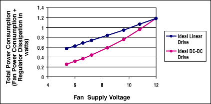
Figure 7. Total power consumption of the Nidec TA225 12V fan plus drive circuitry.
High-Side versus Low-Side Drive
All three methods above can be designed using a high-side or low-side drive transistor (see Figure 8). High-side drive requires slightly more complex circuitry due to level translation, but it has the advantage of keeping the fan's negative terminal at ground. Therefore, speed and alarm sensors are now ground-referenced and it is easier to interface to them.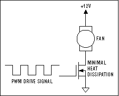
Figure 8a. PWM drive, low side.
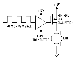
Figure 8b. PWM drive, high side.
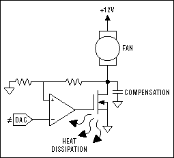
Figure 8c. Linear regulation, low side.
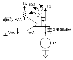
Figure 8d. Linear regulation, high side.
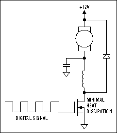
Figure 8e. DC-DC mode, low side.
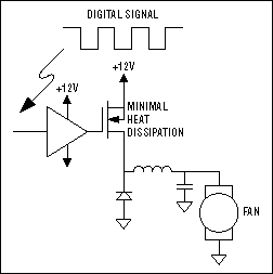
Figure 8f. DC-DC mode, high side.
Low-side drive, on the other hand, doesn't require a level translator for the drive transistor, but will need some type of translation for speed and alarm sensors. With a low-side drive transistor, the positive terminal of the fan is kept at a constant 12V (assuming a 12V fan), while the negative terminal of the fan is adjusted up and down to control speed. Unfortunately, speed and alarm sensors share the fan's negative terminal and get adjusted along with fan speed, resulting in the need for level translation.
Some Applications
Speed Control without a Tachometer
Figures 9 and 10 give two examples of fan circuits designed for systems that don't require an alarm or speed sensor. In the first circuit, the MAX1669 is configured to drive the fan in PWM mode. The second diagram shows the MAX1669 configured for DC linear mode.The MAX1669 is both a temp sensor and a fan controller.
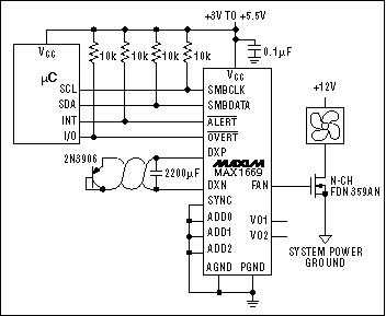
Figure 9. The MAX1669 configured to drive the fan in PWM mode.
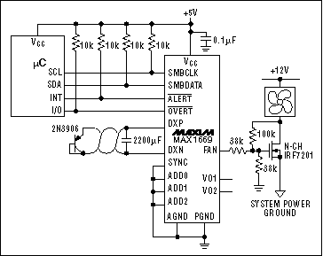
Figure 10. The MAX1669 configured for DC linear mode.
These two blocks work independently from each other and are intended for use with a microcontroller. Communication between the MAX1669 and the microcontroller are done via an SMBus™-compatible interface. The SMB interface is a 2-wire serial interface, which is very similar to and usually backward compatible with the I2C interface.
Temperature sensing is done external to the MAX1669 with a remotely mounted diode. Figure 9 shows a MAX1669 using a 2N3906 connected as this diode. A similar diode is sometimes included on the die of some ICs. An example is Xilinx's Virtex family of parts. These parts have two pins labeled DXN and DXP. Connecting the MAX1669 directly to these pins permits it to measure die temperature directly. This allows the fan circuit to control a particular IC's die temperature more tightly. It also eliminates worries about mounting temperature sensors to IC packages, thermal time constants, and having to do thermal resistance calculations.
This circuit (and others shown later) either runs open or closed loop with respect to temperature. When running open loop, the temperature sensor is used to measure ambient temperature by mounting the sensor at the inlet of the unit. As the ambient temperature rises, fan speed is increased under software control. In this configuration, increasing or decreasing the fan speed will ideally have no effect on the measured temperature. Thus, the system has no form of thermal feedback and is open loop. Because it is open loop, there are no stability issues, resulting in a simpler software design. Everything has a price, however, and there is no direct way of knowing the actual temperature of the components that need to be cooled. If cooling efficiency is reduced due to partially clogged inlets or fan aging, for example, this type of control would have no way of knowing and therefore compensating for it. This means the system must be designed so that the fans spin faster than probably needed, resulting in a less-than-optimum system.
Placing the temperature sensor in a location that the fan is designed to cool forms a closed-loop system. Increasing the fan speed results in a drop of the measured temperature. This now requires attention to stability issues. Such attention leads to longer development time and greater software complexity, but rewards you with a direct and tighter control of your heat source. Now fan speed can be regulated at the minimum speed necessary to keep critical components below a predetermined temperature. In addition, there will be automatic compensation for problems such as partially clogged inlets and outlets. In both cases, the hardware design is the same. The only difference is the placement of the temp sensor and the software code.
Speed Control with a Tachometer
The above circuits work well in lower-end systems where we aren't overly concerned with reliability. However, in systems in which we place a premium on reliability, these circuits can fall short. In the case of open-loop temperature control, the system has no way to detect any type of fan failure. Elevated temperatures in closed-loop control can be used as an indication, yet there is still room for improvement. Elevated temperatures indicate a system problem, but cannot distinguish between clogged inlets and outlets, high ambient temperatures, excessive internal heat dissipation, or fan failures. In addition, as heat is the main indication of problems, it may take a while before these problems are noticed due to slow thermal response. An example would be a pencil suddenly getting stuck in the fan. It may take several minutes before the temperature rises high enough for the problem to be flagged.Tachometer outputs (speed sensors) can address these issues. Figure 11 shows a circuit that uses a fan with a tachometer. The MAX6625 measures the temperature and reports it to the microcontroller via an I2C-compatible 2-wire interface. The same 2-wire interface issues commands to the MAX6650, which controls the speed of the fan. The MAX6650 has all the necessary level translation and hardware to interface with the fan's open-collector tachometer. Fan speed can be read over the SMBus-compatible interface as a byte-wide integer.
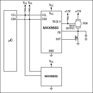
Figure 11. The MAX6650 interfaces to fans with tachometer outputs to monitor and control fan speed. A MAX6625 can be connected to the same I2C-compatible bus to monitor temperature.
The MAX6650 can be configured to work as a fan speed controller or a fan speed regulator. The difference is a subtle but important one. A fan speed controller controls the voltage across the fan and therefore indirectly controls its speed. A fan speed regulator actually measures and regulates the speed of the fan using its tachometer. When the MAX6650 is used as a fan speed controller, a microcontroller reads the temperature from the MAX6625, and the fan speed from the MAX6650 via the SMBus-compatible interface. It then issues DAC codes to the MAX6650. These DAC codes directly control the voltage across the fan and thus indirectly control its speed. The microcontroller must then constantly read the fan speed via the MAX6650 and make adjustments to the DAC to keep the fan's speed in regulation. This becomes especially important around the startup and stall speeds of the fan.
When the MAX6650 is configured as a fan speed regulator, the microcontroller issues speed commands. The MAX6650 automatically monitors and adjusts the speed of the fan to keep it within regulation. Once a desired speed is written, no further involvement by the microcontroller is required. This reduces software overhead significantly. In case the MAX6650 cannot maintain the desired speed, it can be configured to generate an alarm in the form of an interrupt to the microcontroller.
Like the circuits in Figures 9 and 10, these circuits can be made to run in temperature open- or closed-loop systems. It's important to note that in a temperature closed-loop system, there are now two closed loops: one for temperature regulation and the other for fan speed regulation. Additional care must be taken to prevent stability issues from arising.
Because fan control typically relies on a microcontroller, it also depends on software. Software can exhibit many types of problems, including loops of an infinite variety. In PC-based systems, there is even the possibility of viruses intentionally causing problems. Such problems can require some type of backup to prevent damage. Figure 12 shows such a backup.
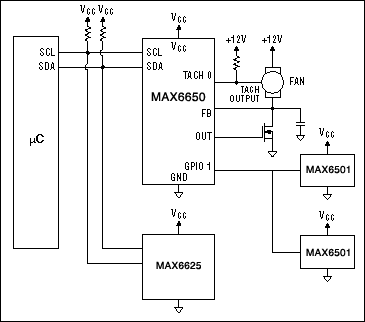
Figure 12. Adding a MAX6501 temperature switch to the circuit in Figure 11 provides a fail-safe temperature backup that works independent of software.
The MAX6501 is a small, inexpensive, digital output temperature sensor. When the temperature rises above a certain threshold, its output pulls low. The MAX6650 can be configured to monitor its GPIO1 (general-purpose input/output) pin such that when it gets pulled low, it will automatically turn the fan on full speed. This will happen independently of commands issued via software. By strategically placing the MAX6501 in critical areas, problems can be avoided. It's interesting to note that this type of backup protection not only will protect against software problems but also against less likely primary temperature sensor failure and microcontroller hardware failure. Because the MAX6501 is open-collector, multiple devices can be tied together and mounted in several places within the unit. This allows multiple critical locations to be protected at once.
Multiple Fans Controlled as a Group
Figure 13 is a variation of Figure 11. It is sometimes desirable to control multiple fans as a single group. Figure 13 shows a MAX6651 controlling three fans as one unit. The MAX6651 is similar to the MAX6650, but has additional GPIOs and tachometer-monitoring inputs. As all three fans are run in parallel, independent speed regulation of each fan is not possible. One fan must be chosen as a master, around which any speed regulation loop is closed. When in regulation mode, the MAX6651 closes the speed loop around the fan connected to Tach0. When the MAX6651 is used as a fan speed controller, the microcontroller can close the loop around any one of the fans. Although the MAX6651 does not directly regulate the speed of the remaining fans, they will tend to run at similar speeds if identical fans are used. To ensure that the unregulated fans are working properly, the MAX6651 allows the microcontroller to read the speed of each fan via the SMBus-compatible interface. This way, if any one fan drops out of tolerance, the user can be flagged. The MAX6651 can directly interface to four fans.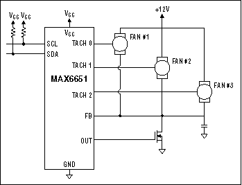
Figure 13. The MAX6651 controlling three fans as one unit.
Figure 14 shows how to use an analog multiplexer to monitor more than four fans. GPIO2, GPIO3, and GPIO4 are configured as outputs. These bits can be toggled via the SMBus-compatible interface to control which fan's tachometer gets connected to the Tach3 input.
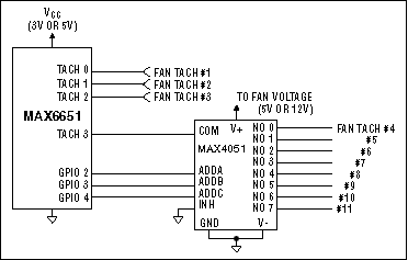
Figure 14. This diagram shows how to use an analog multiplexer to monitor more than four fans.
N+1 and Hot-Swap Application
When a problem does occur with a fan, appropriate action needs to be taken. Sometimes shutting the system down to prevent damage is all that's required. However, in systems that need to minimize downtime, this isn't a very attractive option. Figure 15 shows an application allowing systems to continue to run even during a fan failure. This circuit uses a technique commonly called N+1. N+1 is the practice of using one more fan than is actually needed under worst-case conditions. This allows sufficient cooling to occur if any one fan fails. In addition, all fans should be placed on separate cards and designed such that they can be hot-swapped in and out. This allows a bad fan to be removed and replaced while the unit is running, preventing any downtime.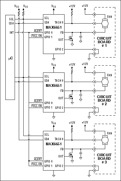
Figure 15. When used in an N+1 application, the MAX6651 can be configured to automatically run all good fans at full speed if one should fail. Also shown is how to configure the circuit to allow for hot swapping.
Because, under most circumstances, more fans are running than are actually required, reducing fan speed becomes even more relevant. However, in the event of a fan failure, the remaining fans need to spin at maximum speed. Also, the user needs to be flagged regarding removing and replacing the bad fan.
In this circuit, the MAX6651s are configured via the SMBus-compatible interface to generate a logic low on GPIO0 whenever they cannot maintain their requested fan speeds. These outputs (which are open-drain with internal pullups) are tied together. Thus, any one of the three fans that cannot be maintained at the desired speed (due to failure) will cause this line to go low. This same line is then tied to all the GPIO1 pins. These pins are configured as inputs that will turn their respective fans on full speed when a logic low is applied. This way, a fan failure automatically results in all fans spinning at full speed. Another benefit is that no involvement is required from the microcontroller.
Although it's unnecessary, it may be desirable for the microcontroller to be interrupted whenever a problem occurs. This is easily accomplished by connecting GPIO0 to the interrupt pin, as shown. By doing this, the microcontroller can now determine which fan has failed by reading their speeds via the SMBus-compatible interface. With this knowledge, it can flag the user to replace the appropriate fan. GPIO2 of the MAX6651 can be read via the SMBus-compatible interface (or through an input pin on the microcontroller if available) to detect when a fan is removed or plugged in.
Synchronizing Fans
Systems that use multiple fans can experience an additional source of noise irritation due to beat frequencies between fans. Similar to the effect experienced in multiple-engine airplanes, two fans that are spinning at slightly different speeds will cause a beating noise whose frequency is related to the difference in speed. This effect can be subtle and is usually not a concern when it comes to most units. However, with higher-end systems, we may want to get rid of as much noise irritation as possible. The obvious solution is to spin the fans at exactly the same speed. Figure 16 shows an application doing just that.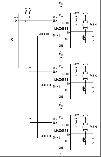
Figure 16. With this application, all the MAX6651s are configured to use the same oscillator, minimizing any speed variations between fans. This lessens beating noises found in multiple fan systems.
The main problem with trying to get independent fans to spin at the same speed is that each MAX6651 has its own time base (oscillator frequency). These time bases are accurate enough to control fan speeds individually, but not accurate enough to prevent beating from occurring in multiple-fan systems. By configuring all the MAX6651s to use the same oscillator, this source of error is eliminated. To facilitate this, the MAX6651 can configure its GPIO2 pin to function as either an oscillator input or output. By configuring the first MAX6651 as a clock output and the rest as clock inputs, they will all run off the same frequency. Now with all parts running with the same clock, speed tolerances can be very tight.
Conclusion
Fan speed control can be used for increasing the reliability, reducing the power consumption, and decreasing the noise of systems. Many different circuits and options can be selected in terms of trade-off in price and performance. The aim of the above discussion was to provide some insight and possible solutions regarding various issues that have to do with implementing such control.A similar version of this article appeared in the September 28, 2000 issue of EDN.
SMBus is a trademark of Intel Corp.