
免费注册参加在线研讨会,学习如何分析、测量并最终解决音频系统的设计问题 (English only) 。
IntroducTIon to the DS1802 Dual Logarithmic Audio Potentiometer
The DS1802 Audio Potentiometer contains two digitally-controlled potentiometers and features a logarithmic taper that produces a 1dB change per increment. The maximum attenuation is 63dB, and it also contains a mute function that attenuates the signal greater than 90dB. Additionally, the DS1802 has four push-button inputs that can be used as either a volume/balance controller for stereo applications or independent position control of the two potentiometers. The part also contains zero-crossing detectors, which when used properly can seamlessly change the volume creating a professional-sounding audio system. The part is available in 20-pin DIP, SOIC, or TSSOP packages.The DS1802 is ideal for applications where a pushbutton controllable resistance is desired, however it also has a 3-wire interface that can be used for controlling the potentiometers by a PC or microcontroller. This application note shows how to use the part with a minimal amount of hardware to create a pre-amplifier circuit with a pushbutton controllable volume for two stereo channels.
Single Power Supply Audio Circuits
The first step in using the DS1802 is understanding how to bias an AC signal to within the DC supply range. This is required because the DS1802 will clip audio signals that attempt to go below GND or above VCC. The DS1802 can operate from a 3V or 5V supply, but be aware that selecting the supply voltage also will affect the maximum audio signal swing that the part can handle. Since audio signals are generally symmetric, it is best to set the DC bias to VCC/2 to obtain the maximum audio signal swing.A Wheatstone-Bridge circuit, shown in Figure 1, can be used to set the DC bias of the input signal to VCC/2.
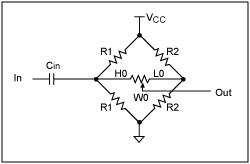
Figure 1. A Wheatstone-bridge circuit for adding a DC bias to an audio circuit.
This circuit is a classic signaling circuit because it allows an AC signal to be passed across the middle resistor (or potentiometer) with the same DC bias on both sides. This is critical for a digital potentiometer because the zero-crossing detector switches the potentiometer's position when there is zero voltage across the end-to-end resistance of the potentiometer. Thus, there is no voltage potential across the digital potentiometer to cause the pop that you will typically hear when a digital potentiometer switches its location instantaneously.
There are three critical performance components to this circuit that can be seen by looking at the AC and DC models shown in Figure 2. First, Cin must be a good capacitor that will block the DC signal. This will allow your DC bias to be set by the resistor network. Additionally, Cin must be sufficiently large to allow low-frequency signals to be passed onto your resistor network. If it is large enough, the system will have good performance over the entire audio range. The second point is that R2 must be much smaller than the end-to-end resistance of the potentiometer. The AC signal will be divided across the potentiometer and the two R2 resistors that will be in parallel. If R2 is large, the majority of the AC signal could potentially be lost and this would decrease the signal to noise ratio of the system. It is advisable to make the two R2 resistors relatively small, however it will obviously affect the DC current of the system as well. The last critical component is that the two R1 resistors should be relatively large or the AC input impedance will be too low for practical use. Most consumer audio components have relatively high input impedances. The size of the R1 resistors and the end-to-end resistance of the potentiometer have the greatest effect on the AC input impedance of this circuit. The input impedance will not be affected that much by R2 or Cin because those impedances must be small with respect to the other two for the circuit to work well.
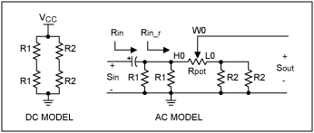
Figure 2. The DC and AC models for the Wheatstone Bridge circuit.
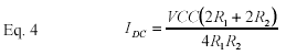
The DC model of the circuit is easy to analyze because the input capacitor isolates the resistor network from any DC associated with the input, and the two ends of the potentiometer are both at VCC/2, so no DC current will flow through the potentiometer. Thus, it is easy to determine the circuit's DC current consumption, which is shown in Eq. 4. It is the sum of the current flowing from VCC to GND through 2R1 and 2R2. The equation has been mathematically simplified to a single fraction. Note that this does not account for the current of the DS1802. It will have a small current due to digital portion of the chip that is not accounted for by this equation.
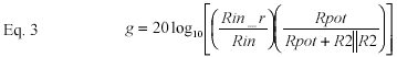
If you consider the AC model for this circuit, VCC will appear as an AC ground, and the resistor is easy to analyze for impedance considerations. The formula for Rin is shown in Eq. 1, and Rin_r (Eq. 2) is the impedance of the resistor network without the input capacitor considered. If you look at the loss formula in Eq. 3, the losses are proportional to Rin_r / Rin and Rpot / (Rpot + R2||R2). The Rin_r / Rin term accounts for the voltage drop from the input capacitor when feeding the input impedance of the Wheatstone-Bridge.
The Rpot / (Rpot + R2||R2) term accounts for the losses associated with voltage divider when the AC signal is divided across the potentiometer and the two resistors bias the low side of the potentiometer. If Cin is large and R2 is small, there will be very little signal loss that is created by this circuit. Also, the only frequency related signal loss would be caused by the input capacitor, which creates a high-pass filter when coupled with the input resistance of the Wheatstone-Bridge resistor network. If the impedance of the capacitor is relatively small compared to the input resistance of the Wheatstone-Bridge, the AC signal will not exhibit frequency-related characteristics. Since the circuit has a tendency to filter low-frequency response, it is wise to calculate how much loss you have at 20Hz. That is the low end of the audio spectrum, and that will give you a good idea of how well your circuit should handle the entire audio range.
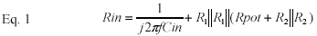
The common mistake that is made when using a digital potentiometer is to attempt to use the part in a way that is normally done with a mechanical potentiometer. Figure 3 shows a simple circuit that can be used with a mechanical potentiometer that will cause popping with a digital potentiometer.
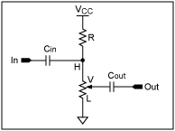
Figure 3. A simple mechanical potentiometer circuit that does not work with a digital potentiometer.
The reason that this circuit works with a mechanical potentiometer is that the DC level of the output signal changes when the potentiometer is changed. The input side of the circuit will remain at a constant VCC/2 DC level (assuming R1 = end-to-end resistance of the potentiometer). When you change a mechanical pot, the change is usually continuously variable. The DC output level changes slowly and continuously. Thus, Cout will allow the AC output signal to remain on DC ground. A digital potentiometer changes potentiometer position instantaneously. The step change in the DC level of the output will momentarily pass current through Cout, and this will cause the popping sound that you will typically hear with a poorly designed circuit. This phenomenon can also be heard with cheap audio circuits that use poor quality mechanical potentiometers that have inadvertent breaks in the resistance during resistance changes. The other issue with this circuit is that it does not enable the zero-crossing detector to work because the high side of the potentiometer (H) is bias to VCC/2, and the low side of the potentiometer (L) is tied to ground. Thus, unless the magnitude of the AC signal is VCC/2, H and L will never be at the same potential, and the zero-crossing detector will always timeout and switch when there is potential across the potentiometer.
Although the above circuit's problems are relatively easy to find, many designs that are very robust mechanical potentiometer designs are often modified to incorporate a digital potentiometer. These types of errors are typical when a circuit is converted. An example of a typical mechanical potentiometer design that may require converting is shown in Figure 4. A couple of things could be potential problems when converting this circuit to a digital potentiometer. The input signal is referenced to ground via the potentiometer. If the input was an audio signal with 0V DC bias, negative signal voltages will be applied to the high side of the potentiometer. The DS1802 would clip signals below ground with its ESD structures. The maximum ratings of the DS1802 would imply that a -0.5V signal would not be a problem. However, the DS1802's ESD-protection circuits are active whenever below GND or above VCC. Although it will not hurt the part, this causes distortion of the audio signal. This circuit would work fine for the zero-crossing detector if both ends of the potentiometer are biased to 0V DC. However, the lack of negative signal swing could cause the circuit designer to decide to bias the input to VCC/2.
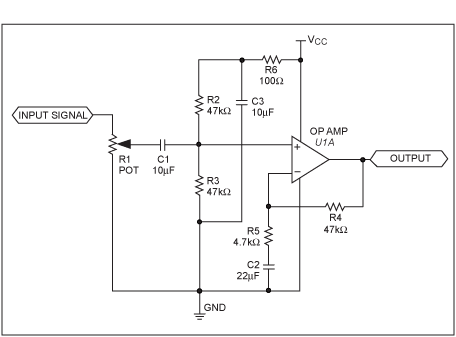
Figure 4. Mechanical potentiometer circuit for conversion to a digital potentiometer.
Once the input is re-biased, you then have the same zero-crossing problem that the circuit of Figure 3 did. The high and low side of the potentiometer are now at different DC potentials, and the instantaneous DC level change at the wiper will propagate through C1 to the output.
The moral of this example is to think through all of the DC operating points and AC signal paths when using a digital potentiometer. The parts are easy to use; however, they are not mechanical potentiometers. They are active components, and must be intelligently used according to the datasheet specifications to achieve good results.
Example Stereo Preamp with Push-Button Volume Control
Beyond the biasing of the audio signal to a DC level of VCC/2, and keeping the high and low side of the potentiometer at the same DC potential, there are few difficulties in making the audio attenuator using a DS1802. The input impedance of the Wheatstone Bridge must be large enough that an external source can drive the signal into the pre-amplifier. The input capacitor must be large enough that it does not attenuate your low-end frequency response, and R2 must be small enough that it does not attenuate your signal across the digital potentiometer.The circuit shown in Figure 5 has minimal signal loss and good frequency response.
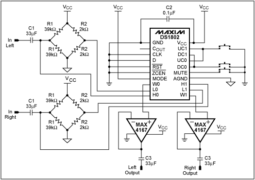
Figure 5. Preamp circuit with push-button attenuator.
Analyzing this circuit yields an input impedance of greater than 13.7kΩ. The signal loss due to the Wheatstone-Bridge circuit and the input capacitor at 20Hz is 1.2dB. Since most full-range speakers at best have a frequency response down to 50Hz, the input attenuation at 50Hz is 0.6dB. Also notice that momentary switches are simply connected to ground since the DS1802 internally debounces input switches. The switching configuration shown provides only the volume up, volume down, and mute control for the audio signal. The DS1802 data sheet shows how to configure the part for a stereo controller and how to independently control the potentiometers using the push-buttons if that functionality is desired. Also note that VCC is de-coupled with a capacitor near both the DS1802 and the MAX4167 operation amplifier. This improves the system's audio performance by limiting supply fluctuations. The operational amplifiers are required in this circuit because the DS1802 has a relatively high wiper (output) resistance. Without buffering, the DS1802 can only drive a 1mA load. Additionally, if the load is capacitive, the high output resistance will cause the attenuator to filter out high frequencies. Since the operational amplifier has a high input impedance, it does not load down the potentiometer and it is capable of providing a reasonable amount of drive current to the next amplifier stage. The two C3 capacitors are required to allow the next stage of the amplifier to re-bias the DC level of the audio signal. They are not required if an input capacitor is present at the next stage, or if the next stage operates at the same DC bias level.