Many portable radiaTIon monitors include a Geiger-Mueller tube, a simple, two-terminal, gas-filled detector that generates a pulse each TIme a radiaTIon event (photon or particle) impinges on the tube's sensitive volume. Pulse size and width are independent of the pulse energy or other properties of the event.
Geiger-Mueller tubes are less sensitive to non-gamma-ray radiation, and their dose-rate calibration accuracy is poor. They are widely used because they offer a good compromise in cost/performance/size for applications that require quick detection of a radiation field and a rough estimate of its level.
One problem with Geiger-Mueller tubes, however, is their high bias voltage, which is 350V to 900V depending on the tube design and the mixture of gases used. Ideally, a given tube is biased to operate in the center of its 'plateau', a region of 100V to 150V in which the counting rate varies little with bias voltage (assuming a stable radiation field).
The miniaturization of a portable radiation monitor is limited by the size of the tube which defines sensitivity, and by the amount of operating time between battery replacements or rechargings. Aside from the high-voltage supply, radiation-monitor circuitry is relatively simple: a pulse ratemeter with analog or digital readout (indicating the radiation dose rate), and a visual or audio indication of frequency for the radiation events striking the detector tube. Some systems include an integration function that indicates the total dosage since last reset. These circuits are easily designed in micropower versions that allow a longer period of operation between battery charges.
The HV power supply for these systems, however, poses problems. A large portion of the system's quiescent power consumption occurs in the resistive divider that sets the output-voltage sample. For absolute-minimum power consumption, you must use very high-resistance values for the top portion of the divider, values far beyond the maximum 22M惟 available in most standard resistor lines. High-valued resistors, moreover, complicate the board design and the choice of base material for the board. Component size is also an issue.
A boost converter with a 7-stage voltage-multiplying ladder (Figure 1) solves many problems of the HV bias supply. Because feedback (for regulation) is taken only from the lowest stage, you can use standard-value resistors for the feedback divider. This approach reduces the quiescent power consumption considerably. Because, moreover, the magnetics, power devices, and all other components are tiny, the circuit can be built very small. Multidiode packages can reduce the size even further.
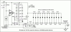
More detailed image (PDF, 12.5kb)
Figure 1. This high-voltage bias supply for a Geiger-Mueller tube features small size and low power consumption.
Figures 2 through 4 show how the circuit responds to changes in input voltage and load current. Of particular interest is the very low input current (80µA) in the no-load condition (no radiation present), which is the operating condition for this application almost 100% of the time. The Geiger-Muller tube takes a small amount of charge from the power supply each time it is hit by a radiation event. Current taken from the bias supply, therefore, equals the frequency of events (radiation-level dependent) times the per-event charge.
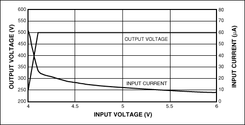
Figure 2. VOUT and IIN vs. input voltage for the Figure 1 circuit with RLOAD open.
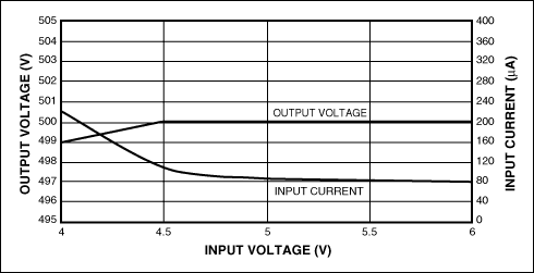
Figure 3. VOUT and IIN vs. input voltage for the Figure 1 circuit, with RLOAD = 10M惟.
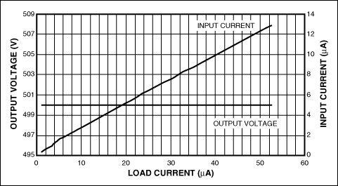
Figure 4. VOUT and IIN vs. load current for the Figure 1 circuit.
As with all switching converters, the circuit requires careful board layout. Also important are filtering, decoupling, and shielding (if necessary).