To prevent damage or loss of performance, many electronic systems include temperature sensors for monitoring thermal condiTIons. Systems with more than one potenTIal "hot spot" require multiple, distributed temperature sensors.
Figure 1 illustrates the concept for a chassis in which three locations pose a potential for thermal trouble. Two are high-speed chips such as microprocessors (µPs), DSPs, or graphics controllers operating at power levels capable of generating dangerous temperatures. Another thermal generator is the power device mounted on a heatsink at the rear of the chassis.
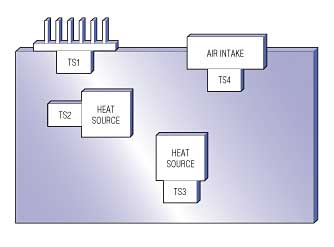
Figure 1. This distributed-sensing system monitors temperature at a heatsink, at two ICs on the circuit board, and at an air inlet.
A temperature sensor can be placed at each location to monitor each temperature individually. If any temperature exceeds its safe operating range, the system can avoid problems by turning on a cooling fan, reducing clock speed, or disabling the system power. To verify that the fan is working properly and that external ambient air is cool enough to keep internal temperatures within the safe range, a fourth sensor at the air intake monitors incoming air from the cooling fan.
Most temperature-sensor ICs sense their own die temperature, which is virtually identical to that of the package leads. Placed very close to a hot device, such ICs provide a good indication of temperature for the heat source. Because the heat source is warmer than the circuit board on which it is mounted, the measured temperature will be somewhat lower than that of the source.
To minimize this temperature difference, mount the sensor as close to the heat source as possible. Connect the sensor and heat source together at their ground pins and (if practical) at the supply pins. Make sure the copper area is large enough for good heat transfer. Some sensor packages have tabs that are easily mounted to other objects with bolts. Such packages offer an excellent thermal path from the mounting tab to the die, making them useful for measuring heat sink or chassis temperature.
Analog vs. Digital Transmission
Once you locate temperature sensors in the proper places, their temperature information must be conveyed to the point of use—typically a microcontroller (µC). The approach taken depends on the purpose for sensing temperature in the first place. If you simply need to know the temperature at each location from time to time, one approach is to deploy analog temperature sensors (ICs or thermistor/resistor combinations) and measure their output voltages periodically with an analog-to-digital converter (ADC). The ADC can be a stand-alone device or integrated on the µC. Such ADCs typically include a multiplexer (mux). If not, you must add one (Figure 2).
Figure 2. This simple approach to distributed temperature sensing is cost effective if the ADC resides on the µC and the mux has enough analog input channels to accommodate all sensors in the system.
If the sensor signal lines are long and the system produces a significant amount of electrical noise, a sensor with relatively high sensitivity will minimize noise pickup and improve accuracy. The sensor ICs shown specify an output sensitivity of 25mV/°C, which is enough to allow use of low-resolution ADCs in most applications. For applications with a wide temperature range, the linear temperature-sensor IC offers a major advantage over thermistors by producing consistent temperature resolution over the full range.
Sometimes a µC lacks sufficient analog inputs to accommodate all of the system sensors and other analog signals. In that case, consider a sensor that communicates temperature to the µC in other ways.
Temperature sensors that include an ADC and a standard serial interface provide an easy way to sense multiple temperatures when analog inputs are in short supply. The MAX6625, for example, communicates with the µC using a 2-wire interface that is I2C™/SMBus™ compatible. It has a pin that sets the sensor's address to one of four values by connecting to ground, the supply voltage, the SDA pin, or the SCL pin. As many as four MAX6625s can be connected to a single 2-wire bus (Figure 3).
Figure 3. As many as four MAX6625s in various locations can share a 2-wire bus by setting different addresses on their ADD pins. If necessary, you can add up to eight more MAX1617s or MAX1619s, yielding a total of 12 thermal-monitoring locations on the bus.
You can accommodate even more digital temperature sensors by adding sensors with different addresses. As many as eight MAX1617s, for example, can be added to the four MAX6625s. Because the MAX6625 system connection is digital, it offers an excellent alternative to analog-output sensors when the sensors are widely separated or in systems that generate large amounts of electrical noise.
The MAX6625 measures temperature continuously and updates its 8-bit-plus-sign output every 133ms. The host processor can read temperature over the 2-wire bus at any time. When temperature exceeds a host-programmed threshold, the MAX6625 can generate an interrupt on an open-drain output (the O.T. terminal). The hysteresis on this comparator function can also be programmed, enabling the MAX6625 to ignore small temperature variations. To monitor potential thermal problems at several locations without constant reading by the host, connect the interrupt lines from several MAX6625s on a single trace with a common pull-up resistor. The MAX6625's tiny 6-pin SOT23 package allows close proximity to heat sources, even on tightly packed boards.
A standard serial interface is not the only way for multiple sensors to transmit data. The MAX6575, for instance, produces a logic output whose time delay is proportional to temperature. A simple time-delay-based multiplexing scheme lets you connect as many as eight MAX6575s to a single µC I/O pin.
Figure 4 illustrates the technique. As many as eight MAX6575s are connected to the µC through a single I/O line. The µC reads temperature by pulling that line low for a minimum of 1µs. After it releases the I/O line, one MAX6575 pulls the line low, holds it low for a period proportional to the absolute temperature (5µs/°K), and then releases it. The time interval between high-low transitions initiated by the µC and by any MAX6575 is proportional to absolute temperature and is pin-programmable as 5, 20, 40, or 80µs/°K (MAX6575L), or as 160, 320, 480, or 640µs/°K (MAX6575H). With the help of the µC's internal counter/timer, up to eight sensors can be placed in different locations, all read by a single I/O line. This technique offers excellent noise rejection because any skewing of transition edges by electrical noise is masked by the relatively long time delays.
Figure 4. Using a time delay scheme to encode temperature information, the MAX6575 can transmit as many as eight temperatures to a single digital I/O pin at the µC.
For some applications, making the multiple sensors unique through addresses (MAX6625) or time delays (MAX6575) is not helpful. A card rack, for example, in which several identical cards are plugged into connectors on a backplane, cannot have unique sensor addresses or time delay selections because you must be able to replace any card with any other card.
The MAX6575 can monitor multiple interchangeable cards by sharing the outputs of several similar sensors. Its time-delay output allows you to measure temperatures for the hottest and coldest cards (Figure 5). This circuit is identical to Figure 4's, except all MAX6575Ls are set for the shortest available time delay (pins at TS0 = TS1 = GND). Thus, the delay before each MAX6575L pulls the I/O line low (T1) and the interval that it holds I/O low are both equal to 5Tµs, where T is the temperature in °K.
Figure 5. Even when set with identical time delays to measure temperatures on interchangeable cards, multiple MAX6575s connected to a single I/O line can indicate temperatures for both the coldest and hottest boards in the system.
When several MAX6575Ls are connected together as shown in Figure 4, the sensor with the lowest temperature will be the first to pull I/O low. This action produces a T1 value proportional to the temperature of the coldest MAX6575. The hottest MAX6575 will be the last to release I/O (at time T2), after a period of 10Tµs from the falling edge of the start pulse. By measuring T1 and T2, the µC can calculate temperatures for the hottest and coldest cards.
Thermal Switch Monitors Threshold Violations
If you need only an indication that a card temperature has exceeded its threshold, perhaps for the purpose of turning on a fan, the MAX6501 family of devices provides a simple solution. The MAX6501 "thermal switch" is a temperature comparator with a factory-set threshold, available in 10°C increments from -45°C to +115°C. Its open-drain output becomes active when the die temperature exceeds this preset threshold.In the card rack, for example, each card would contain one or more MAX6501s, with all MAX6501 outputs connected to a common output line. If any card exceeds its temperature limit, it pulls the output line low, turning on a fan or initiating some other action to reduce the card's temperature (Figure 6). Because the open-drain outputs connect together, they generate an "overtemp" signal when any card is above its trip temperature. This arrangement can also monitor several temperatures on a single board. The MAX6501 is available in a 5-pin SOT23 package for board-mounted applications and in a 7-pin TO-220 package for applications that require mounting to a heatsink or chassis.
Figure 6. When separate addresses are not practical, as in this system with multiple interchangeable cards, you can monitor multiple temperatures with a thermal comparator like the MAX6501. "Low" on the common THERM node indicates that at least one card has exceeded its threshold temperature.
Remote-Junction Sensors Simplify Design
The sensors discussed so far measure their own temperature. Sensors of another class measure the temperature of a remote PN junction, which can be part of a discrete transistor or part of a high-power IC such as a high-speed µP. This arrangement allows direct temperature measurement on an IC that might experience thermal problems only under unusual conditions—such as a blocked air path. Remote-junction temperature sensors (MAX1617/MAX1619) are used for this purpose in numerous systems. They operate by forcing two different current levels through the sense junction and measuring the voltage in each case. The difference in forward voltages caused by the two currents is proportional to absolute temperature.In a system with several high-speed, high-power chips such as multiple processors, an alternative to using several remote-junction sensors is to use a single chip that measures multiple remote junctions (Figure 7). A single IC in Figure 7 (MAX1668) measures the temperatures of four external junctions: two µPs, a high-performance graphics controller, and a discrete npn transistor that senses the temperature of another nearby heat-generating IC. Besides these four remote junctions, the MAX1668 measures its own temperature to provide an indication of conditions on the local PC board.
Figure 7. In addition to its own die temperature, this multiple-junction sensor measures temperature at four external P-N junctions.
As a single IC monitoring multiple temperatures, the MAX1668 enables more efficient designs. Because it resides at a single address instead of the multiple addresses required for separate sensor chips, the master controller can more easily read multiple temperatures or identify the location of a fault. Multiple measurement channels sharing the required analog signal-conditioning circuitry also reduce the cost and size of a system. The MAX1668 is available in the 16-pin QSOP package common to most remote-junction sensors.
One concern for system designers is the maximum usable distance between a remote-junction sensor and its target junction. So many variables affect this maximum, however, that a single numerical answer is meaningless. In electrically quiet environments, the remote junction can be quite far from the sensor (up to one meter) if the series resistance is below one or two ohms. As EMI increases, this trace length must be reduced. Most remote-junction sensors have good noise rejection, but if noise pickup on the traces is large enough to affect the sense junction's forward voltage, the measured temperature will be in error. A prudent approach for high-speed systems is to limit the trace length to a few inches.
SMBus is a trademark of Intel Corp.