Reference Design for a PC-based Temperature-Measurement System
Abstract: The MAX6603 and MAX1396 EV kits can be used to implement a PC-based temperature measurement system by following the connecTIon methods outlined herein coupled with an easy to use software program attached. The MAX6603 converts ambient temperature to voltage signal by using two plaTInum thermistors. The MAX1396 EV kit provides the analog-to-digital conversion to measures the output voltage signal from the MAX6603 EV kit and sends it over to the PC. The software converts the received data to temperature values and displays it on the screen.
IntroducTIon
This reference design describes how to create a PC-based temperature-measurement system for evaluaTIng the MAX6603 signal conditioner. The design uses two EV (evaluation) kits, the MAX1396EVKIT and a MAX6603EVKIT, and an easy to use software program.The MAX6603 converts ambient temperature to a voltage signal by using two platinum thermistors. The MAX1396 EV kit provides the analog-to-digital conversion to measure the output voltage signal from the MAX6603 EV kit. Then the MAX1393 EV kit sends that signal to the PC. The software converts the received data to temperature values which are displayed on the screen.
Setup Overview
MAX6603
The MAX6603 is a dual-channel, platinum, RTD-to-voltage signal conditioner. It excites and amplifies the signal from two series-connected on-board 100Ω platinum resistive temperature devices (Pt RTD) to achieve high-voltage, level-filtered signals for temperature measurements. This reference design uses the MAX6603 EV kit to measure the temperature. The Pt-RTDs mounted on the EV kit board can be electrically disconnected from the circuit by removing the shunt on JU4 and allowing an external Pt-RTD to be connected to the MAX6603 through twisted-pair cabling.MAX1396
The MAX1396 is a 312.5ksps, 2-channel single-ended, 12-bit SAR ADC. It is used in this design to measure the output voltage from the MAX6603 EV kit. Please follow the instructions in the MAX1396 EV kit data sheet to install the EV kit.Hardware
Apply a +6V to +9V voltage supply to the HVIN pad of the MAX6603 EV kit, and connect the negative terminal of the voltage supply to the GND pad. The OUT1 and GND pads of the MAX6603 EV kit need to be connected to the AIN1 and the GND pads of the MAX1396 EV kit. Use a USB cable to connect the MAX1396 EV kit to the PC. Figure 1 shows the hardware system setup.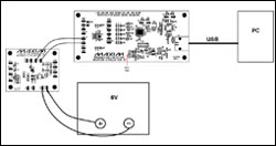
More detailed image (PDF, 416kB)
Figure 1. Hardware system block diagram.
The MAX6603 EV kit consists of the MAX6603, all required passive components, and a proven PCB layout. The MAX6603EV kit schematic is shown in Figure 2 and Table 1 shows the jumper settings.
Figure 2. MAX6603 EV kit schematic.
Table 1. MAX6603 EV Kit Jumper Settings
| Jumper | Position |
| JU1 | 1-2 |
| JU2 | 1-2 |
| JU3 | 1-2 |
| JU4 | 1-2 |
The MAX1396 EV kit consists of one MAX1396 device, one MAXQ2000 microcontroller, all required passive components, and a proven PCB layout. The MAX1396 EV kit schematic is shown in Figure 3 and Table 2 shows the jumper settings.
More detailed image (PDF, 452kB)
Figure 3. MAX1396 EV kit schematic.
Table 2. MAX1396 EV Kit Jumper Settings
| Jumper | Position |
| JU1 | 1-2 |
| JU2 | 1-2 |
| JU3 | 1-2 |
| JU4 | 1-2 |
| JU5 | 1-2 |
| JU6 | 1-2 |
| JU7 | 1-2 |
Windows® Program Overview
This program (Figure 4) has an easy-to-use graphical user interface that is compatible with Windows 98SE/2000/XP. It displays the output voltage of the MAX6603 EV kit and the corresponding temperature readings from the platinum thermistors on the screen.Once the MAX1396 EV kit is connected to the PC through the USB cable, the MAXQ2000 waits for the commands from the Windows program. Start the program and a window similar to Figure 4 should appear. If a message box says, “No Virtual COM Port Detected,” close the program, reconnect the USB cable, and restart the program.
After the software starts up, by default the Auto Read box is checked. The software continuously sends the Read Temp command to the MAX1396 EV kit to measure the OUT1 voltage of the MAX6603 EV kit. The temperature is read at a rate set by the Time Interval pulldown menu. After the software receives the measured OUT1 voltage value, the corresponding temperature value will be displayed in the upper left corner of the screen.
To have more accurate ADC readings, use a digital voltmeter to measure the reference voltage on pin 1 of JU7 on the MAX1396 EV kit. Enter the value into the MAX1396 EV kit reference voltage edit box. If this is done correctly, the ADC readings should have less than 0.1% error.
Measure the actual supply voltage on pin 1 of the JU1 on the MAX6603 EV kit, and enter the value into the MAX6603 supply voltage edit box. This step is important because the formula, which is used to convert the output voltage of the MAX6603 to temperature, depends on the value of the supply voltage.
Figure 4. The reference design's software measures the temperature from the EV kit and voltage from the MAX6603.
Windows is a registered trademark of Microsoft Corp.