
Solid State Power Controller
About the Circuit
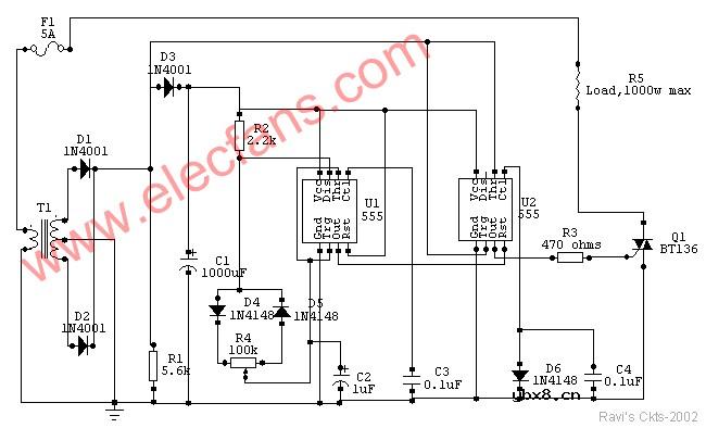
The ckt is built around two 555 timer ICs. U1 and U2. U1 is wired as a variable duty cycle oscillator with a constant time period of around 0.1 second. Duty cycle can be varied from 0 to 100 per cent by R4 potentiometer. The output of U1 (pin 3) is connected to the rest input (pin 4) of U2.
U2 is wired as a comparator with hystereis, i.e a Schmitt trigger. Diode D6 brings the potential at control voltage (pin 5) terminal at 0.7V. The threshold (pin 6) and trigger (pin 2) terminals connected together constitute the input. The output (pin 3) of the Schmitt trigger goes high when Vin equals or below 0.35V and goes low when it is equals or above 0.7V.
Transformer T1 with rectifying diodes D1 and D2 delivers unidirectional AC voltage across R1 with a peak voltage of 8.5V and 100Hz frequency. C1 is the filtering capacitor. D3 prevents the voltage across R1 from being filtered.
Since the input of the Schmitt trigger is connected across R1, its out put will be high when input voltage falls below 0.35V and remains so till it exceeds 0.7V. If pin 4 of U2 is left unconnected, the triac will be fired at the start of each half cycle of AC by a short pulse. Hence full power will be delivered to the load. But since output of U1 is connected to the rest input of U2, the Schmitt trigger delivers pulses to the gate of triac only when output of U1 is high. This explains how variable duty cycle zero crossover switching is accomplished. I have used a 5-amp triac, which is capable of switching loads up to 1000W. Using a triac with larger current rating can also control higher loads. Of course, size of the heat sink will have to be suitably increased.
Construction
You can build this circuit in a general purpose IC strip board. Potentiometer R4 should be linear with a plastic shaft. It can be mounted on the front portion of the enclosure, with a dial marked from 0 to 100 per cent power at, say 5 per cent intervals. If a metallic enclosure is used, care must be taken to ensure that the heat sink of triac does not touch it anywhere.
To avoid shock, do not touch any part of circuitry while in operation.
Components
U1 & U2 - NE555 timer
Q1 - 5A, 400 PIV triac (BT136)
D1-D3 - IN4001 rectifier diodes
D4-D6 - IN4148 switching diodes
R1 - 5.6K
R2 -2.2K
R3 -470 ohms
R4 - 100K linear potentiometer with plastic shaft
(all resistors ¼ watt, 5% tolerance)
C1 - 1000mfd, 12V
C2 - 1mfd, 12V
C3,C4 - 0.1mfd,50V ceramic
T1 - 220V primary 6V-0-6V secondary, 150ma
F1 - 5-amp fuse
(You will have to connect the AC line to T1 primary. I have not shown that)
相关热词:#固态
 什么是感应电机?什么是无刷电机?二者有何区...
时间:2026-10-23
多核DSP的多路同步时钟信号设计
时间:2026-10-23
什么是lcd12864?lcd12864的特性及其应用举例
时间:2026-10-23
 IoT无线连接基础知识
时间:2026-10-23
光是一种电磁波,那么光的频率是多少?
时间:2026-10-22
 DRAM简介
时间:2026-10-22
电容耦合是什么意思呀?
时间:2026-10-22
什么是单总线
时间:2026-10-21
STM32的CAN总线通信实现
时间:2026-10-21
什么是电源管理?有什么作用
时间:2026-10-20
 详解RCD钳位电路
时间:2026-03-08
三相异步电动机原理
时间:2026-03-04
 美的电磁炉电路图大全(六款美的电磁炉电路...
时间:2026-03-07
三相异步电动机的拆装详讲
时间:2026-03-04
 基于逻辑门的构成解释如何完成任意逻辑的管...
时间:2026-03-08
 彩灯电路
彩灯电路
时间:2026-03-05
 光耦在电子电路中作用、关键参数详解
时间:2026-03-08
 从0学电路,万用表演示测量三极管方法
时间:2026-03-08
 NE555的有趣电路设计分享
时间:2026-03-08
 H桥电机驱动电路解析
时间:2026-03-08