
汽车热限制器的烙铁 Auto Heat Limiter for Soldering Iron
|
Wattage of load |
10W |
18W |
25W |
35W |
65W |
80W |
|
Value of R5 (in ohms) |
330 |
180 |
136 (68+68) |
100 |
56 |
44 (22+22) |
|
Wattage of R5 (in watts) |
01 |
02 |
02 |
04 |
05 |
6.5 |
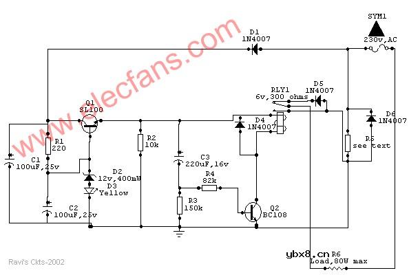
Usually a soldering iron takes a couple of minutes to get adequately heated up to melt the solder, after which the heat generated is much above the requirement and is wasted. Moreover, excessive heat decreases the life of the bit and the element, causing serious damage to the components.
The above circuit solves this problem in a simple and inexpensive way and could be used to various types of loads up to 80watts.
How it works
Once the main is switched on, an approximate 15v drop of the positive half cycle across R5 is detected and supplied to Q1 (SL100 or D313), which acts as a voltage regulator. Zener diode D2 together with diode D3 (yellow LED) stabilizes the emitter voltage of Q1 at 13.2Vdc, which is then delivered to the relay circuit built around Q2 and C3. Capacitor C3 charges through the base-emitter path of Q2 and causes the relay to actuate, which in turn allows both the half cycles of the AC mains to flow through diode D6 and R5 to the load to heat it up at a normal rate.
After a certain lapse of time (about 2 minutes preset) C3 saturates and Q2 stops conducting through the relay, thus switching on series diode D5 to allow only half of the Ac cycle through the load.
After switching off the system, C3 discharges very slowly through R2 and R3. Before C3 gets completely discharged, if the power is switched on again, C3 takes a shorter time to reach the saturation level, thus switching series diode D5 much earlier than the preset time to prevent double heating of the load.
However, if the circuit is switched on only after a few seconds of switching off, C3 gets no time to discharge and the relay does not actuate at all. Moreover, if the relay circuit fails due to any reason and Q2 does not conduct, no harm is done to the load because in that case D5 remains in series with it. Thus the circuit offers complete protection to the load.
As stated earlier, the given value of C3 gives a delay of 2 minutes. However, a 1000mfd capacitor can also be used to produce a 4.5-minute delay. R5 maintains a drop of about 15V across itself. So for use in different load conditions its value changes as shown in Table 1.
The whole circuit can be mounted on a PCB and fitted in an adapter case (7.6cm X 5.1cm X 6.4cm) and used as a mains plug. Since R5 gets heated up during the operation, it should be kept well isolated from the other components.
Components List
R1 - 220 ohms
R2 – 10K
R3 – 150K
R4 – 82K
(all resistors should be 5% close tolerance)
C1- 100 uf, 25V dc working electrolytic
C2 – 100 uf, 25V dc working electrolytic
C3 – 220 uf, 16V dc working electrolytic
(advisable to use close tolerance Caps. to obtain correct timings)
D1, D4, D5, & D6 – IN4007
D2 – 12V 400mw, Zener diode
D3 – Yellow LED
RLY1 – 6V, 300 ohms DC relay
Q1 – SL100 or D313
Q2 – BC108
相关热词:#烙铁
 什么是感应电机?什么是无刷电机?二者有何区...
时间:2026-10-23
多核DSP的多路同步时钟信号设计
时间:2026-10-23
什么是lcd12864?lcd12864的特性及其应用举例
时间:2026-10-23
 IoT无线连接基础知识
时间:2026-10-23
光是一种电磁波,那么光的频率是多少?
时间:2026-10-22
 DRAM简介
时间:2026-10-22
电容耦合是什么意思呀?
时间:2026-10-22
什么是单总线
时间:2026-10-21
STM32的CAN总线通信实现
时间:2026-10-21
什么是电源管理?有什么作用
时间:2026-10-20
 详解RCD钳位电路
时间:2026-03-08
三相异步电动机原理
时间:2026-03-04
 美的电磁炉电路图大全(六款美的电磁炉电路...
时间:2026-03-07
三相异步电动机的拆装详讲
时间:2026-03-04
 基于逻辑门的构成解释如何完成任意逻辑的管...
时间:2026-03-08
 彩灯电路
彩灯电路
时间:2026-03-05
 光耦在电子电路中作用、关键参数详解
时间:2026-03-08
 从0学电路,万用表演示测量三极管方法
时间:2026-03-08
 NE555的有趣电路设计分享
时间:2026-03-08
 H桥电机驱动电路解析
时间:2026-03-08