简单的直流电机PWM调速电路 Simple DC motor PWM speed control
The 555 is ubiquitous and can be used as simple PWM speed control

Circuit Explaination:
The 555 Ic is wired as an astable and the frequency is constant and independent of the duty cycle, as the total resistance (R charge + R discharge, notice the diode) is constant and equal to 22Kohm (givin a frequency of about 1Khz, notice the hum).
When the potentiomenter is all up, the Rcharge resistance is 1,0 Kohm (the diode prevents the capacitor to charge through the second potentiometer section and the other 1,0 Kohm resistor) , and Rdischarge is 21 Kohm, giving a 5% on duty cycle and a 1Khz frequency.
When the potentiomenter is all down, the Rcharge resistance is 21,0 Kohm (the diode prevents the capacitor to charge through the second potentiometer section and the other 1,0 Kohm resistor) , and Rdischarge is 1 Kohm, giving a 95% on duty cycle and a 1Khz frequency.
When the potentiomenter is at 50% , the Rcharge resistance is 11,0 Kohm (the diode prevents the capacitor to charge through the second potentiometer section and the other 1,0 Kohm resistor) , and Rdischarge is 11 Kohm, giving a 50% on duty cycle and a 1Khz frequency.
The 555 provide good current capability to drive the mosfet fast and to drive a bipolar transistor.
I actually use this system to drive the DC motor of my small Rotary spark gap Tesla coil at variable speed
If you are disgusted by the 1Khz hum of the motor try to rise the frequency out of the audible range (replacing the potenziometer), but rembember that at higher frequency inductive reactance of motor rises so the the efficiency would drop.
Important:
Obviously the mosfet (or bipolar) must have enough current capability to drive the motor, so the drain (or collector) current must be equal to maximum motor current (at power supply voltage, when it is blocked). The snubber diode too, because it shorts the motor on the off cycle. Both mosfet (or bipolar) and diode have to be hooked (if you don't want them cooked ;-) ) to a heatsink
if the max motor current is more than 100 or 200mA. I suggest to not stress to much the motor with too much work because it overheats both motor, transistor and diode.
If you don't want braking in the off cycle just place a resistor in series with the snubber diode, it should rise a bit efficiency but have more inertia when slowing the motor down. The value of the resistor must be R=V(breakdown transistor) / Imax, and the power should be 5W. Mosfets have internal zener diode, but don't count on it ;-)
相关热词:#调速电
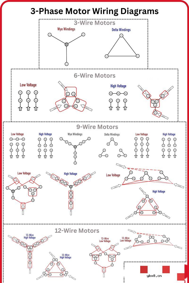 三相电机接线信息图
时间:2026-07-23
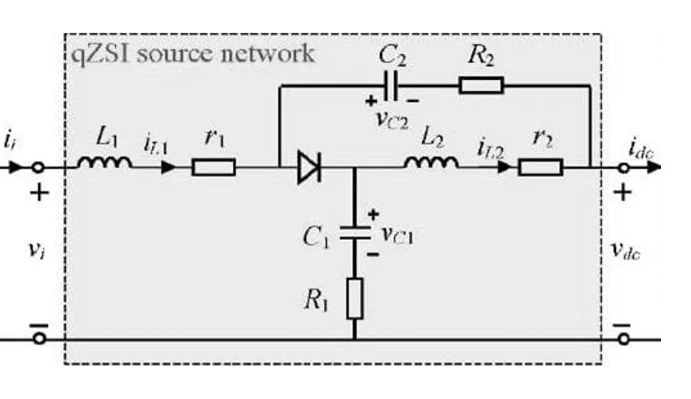 准 Z 源逆变器的设计
时间:2026-07-23
 关于阻容吸收器的简单介绍
时间:2026-07-23
S7-1200和CP343-1的Profinet通信方法
时间:2026-07-23
PDP(等离子显示),PDP是什么意思
时间:2026-07-23
光纤收发器的连接方式和作用
时间:2026-07-22
什么是电磁波?电磁波常见问题
时间:2026-07-22
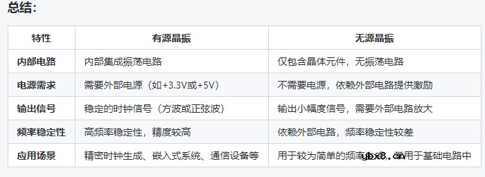 如何区分有源晶振和无源晶振
时间:2026-07-22
什么是“涡流”以及为什么它们对电机很重要...
时间:2026-07-22
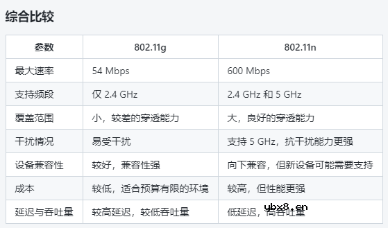 802.11g和802.11n的选择分析
时间:2026-07-21
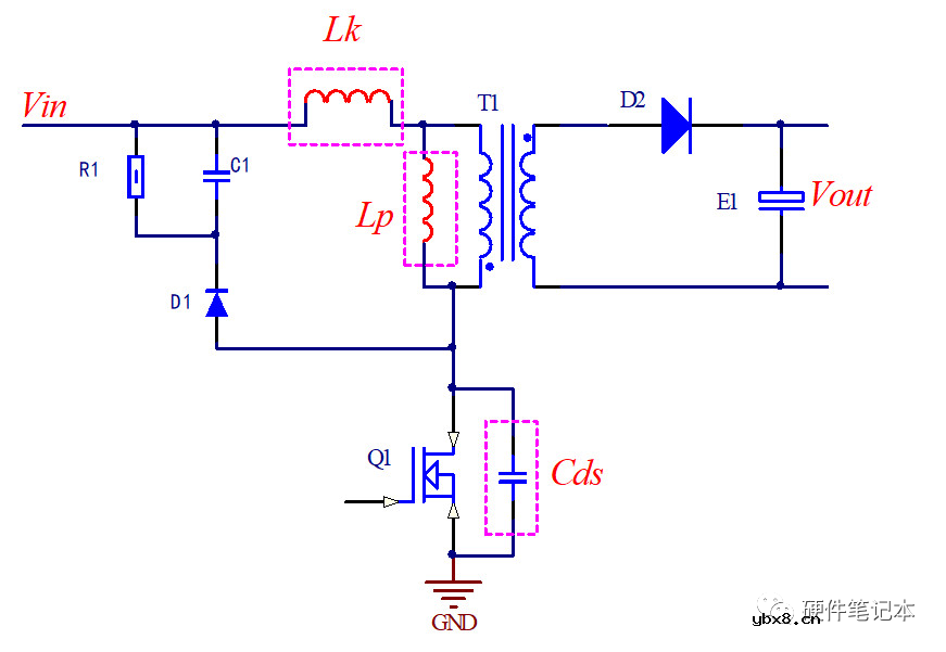 详解RCD钳位电路
时间:2026-03-08
三相异步电动机的拆装详讲
时间:2026-03-04
三相异步电动机原理
时间:2026-03-04
 基于逻辑门的构成解释如何完成任意逻辑的管...
时间:2026-03-08
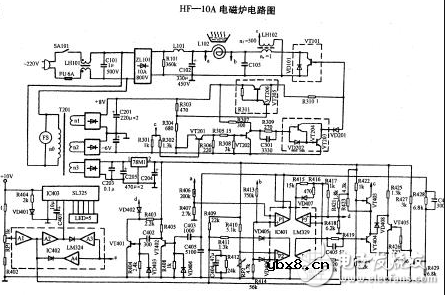 美的电磁炉电路图大全(六款美的电磁炉电路...
时间:2026-03-07
 彩灯电路
彩灯电路
时间:2026-03-05
 NE555的有趣电路设计分享
时间:2026-03-08
 从0学电路,万用表演示测量三极管方法
时间:2026-03-08
 光耦在电子电路中作用、关键参数详解
时间:2026-03-08
 H桥电机驱动电路解析
时间:2026-03-08