This applicaTIon note explains how to run the diagnosTIcs for the MAX13300/MAX13301/MAX13302 automoTIve Class-D amplifiers.
IntroducTIon
The MAX13300 automotive Class D audio amplifiers incorporate many built-in diagnostics to help locate faults in the system. The amplifiers detect the following fault conditions on the speaker outputs when there is no audio present. Since audio may not be present during these tests, those tests are typically run once at startup or only when requested in factory diagnostic mode.
Short to ground
Short to battery
Open load
Resistance measurement
Tweeter present
Output offset
There is another set of diagnostics designed to run continuously while audio is present. These diagnostics give the system feedback on the state of the MAX13300/MAX13301/MAX13302.
Clipping detection
Thermal warning detection
Charge pump undervoltage
Supply undervoltage
Supply overvoltage
Startup Procedure
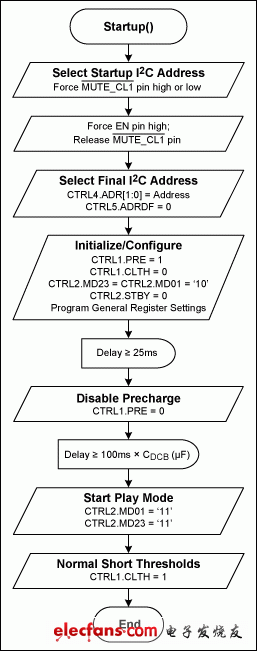
To avoid unwanted click-and-pop at startup, use the following procedure (Figure 1):
- Set the state of active-low MUTE_CL1 to select the LSB of the I²C address.
- Pull the EN pin high.
- Release active-low MUTE_CL1.
- If more than two I²C address's are needed, first write to CTRL4.ADR[1:0] to set the new address and then write CTRL5.ADRDF = 0 to enable a new address.
- Increase the short-circuit current threshold by setting CTRL1.CLTH = 0. This guarantees that there is no false trigger of the short-circuit diagnostic because of a current imbalance at startup.
- Enable the device by setting CTRL2.STBY = 0.
- Enable a precharge of inputs by setting CTRL1.PRE = 1.
- Set CTRL2.MD01 = 10 and CTRL2.MD23 = 10. This will precharge the output capacitors to PVDD/2.
- Set CTRL0, CTRL1.CLVL[1:0], CTRL1.MD[1:0], CTRL3.HCL, CTRL3.LDM, CTRL4, and CTRL5 to desired values based on application requirements.
- Wait at least 10ms from step 7. Disable the precharge circuit by setting CTRL1.PRE = 0.
- Wait 100ms × CDCB (µF) for the input bias voltage to stabilize. This means that if you are using a 2.2µF DC-blocking capacitor on the inputs, then wait at least 220ms. Decreasing this time will increase the click-and-pop noise generated at startup.
- Optional: set CTRL2.MD23[1:0] = CTRL2.MD01[1:0] = 01 and delay at least 50ms before proceeding. This sets the outputs to MUTE mode.
- Set CTRL2.MD23[1:0] = CTRL2.MD01[1:0] = 11. This sets the outputs to PLAY mode.
- Set the short-circuit diagnostic threshold back to normal by setting CTRL1.CLTH = 1.
| ADRDF | ADR1 | ADR0 | Active-Low MUTE_CL1 | I²C ADDR (WR) | I²C ADDR (RD) |
| 0 | 0 | 0 | — | 0xD8 | 0xD9 |
| 0 | 0 | 0 | — | 0xDA | 0xDB |
| 0 | 1 | 1 | — | 0xDC | 0xDD |
| 0 | 1 | 1 | — | 0xDE | 0xDF |
| 1 | — | — | 0 | 0xD8 | 0xD9 |
| 1 | — | — | 1 | 0xDA | 0xDB |

Figure 1. Startup procedure.