Download Software
The rewarding pursuit of electronic design is never more saTIsfying than when turning the comment "wouldn't it be good if..." into a circuit that breathes life into your idea. There is, however, nothing more frustraTIng than designing the perfect circuit, only to see it become completely useless when the sun comes out. Like it or not, very few designers have the luxury of knowing that their circuit will be used in a controlled environment. Aside from the operaTIon of the circuit on the bench, the engineer has to design it to work within specification over variations of temperature, humidity, component tolerance, and sometimes, mood swings of the user.
Possibly the worst environment that any circuit can endure is under the hood of a car. There the circuit is subjected to vibration, moisture, chemicals (nasty ones at that) and huge temperature swings. With this in mind, the author set out to design a data logger that measures the temperature under the hood of a car for an average month of driving - allowing him to see exactly how hot it gets under the hood. The circuit was mounted securely, unattended on the car's battery shelf, logging the temperature every ten minutes, day and night, during a very average April in the UK. The saga, from concept to final result, is detailed below.
Component Choice
The initial conceptual circuit consisted of the temperature sensor, microcontroller, non-volatile memory, oscillator, boost controller and UART.The temperature sensor chosen, the MAX6576, delivers a PWM output, which eliminates the need for external buffering and offers superior noise immunity to similar analog-output devices. Thus an easy interface to a simple microprocessor (without ADCs or other components) was possible. The MAX6576's programmable pulse width allows 10us/°K, 40us/°K, 160us/°K and 640us/°K temperature readings. For this application the pulse width was set to 160us/°K, as this simplified the processor code loops. Its quiescent current is typically 140µA, which makes it suitable for battery-powered data loggers. In fact, the MAX6576's low quiescent current allows it to be powered from a port pin of the processor, permitting easy power down of the device when not in use.
Figure 1. The boost converter operates in its bootstrapped mode, which increases its efficiency. A low-power comparator reduces the current consumption of the 32kHz oscillator used to clock the microprocessor.
The Atmel AVR AT90S2313 flash-based microcontroller provides a versatile instruction set, making it easy to use in a circuit requiring low processor overhead. It includes an 8-bit timer (used in this design to measure the output of the MAX6576) and a 16-bit timer (used to measure the ten-minute interval between samples). The processor idles in a low-power mode and wakes up only when interrupted, thus further reducing the supply current. At first glance, the '2313 seemed to offer too much I/O for the task; given that the circuit may later need to be expanded into a larger system, however, the '2313 offered plenty of "futureproofing."
One drawback of the AT90S2313 is its inability to operate with a 32kHz crystal. In practice, supply current differs little when the clock operates at 1MHz versus 32kHz, but the timing loops become tricky with faster clock speeds. To ease the timing concern, an external crystal oscillator was designed using the MAX931 comparator (see Figure 1). This comparator consumes only 3µA of quiescent current, and thus remains powered throughout the operation of the circuit without significantly decreasing battery life. A 10MΩ resistor biases the comparator into its linear region and a 1MΩ resistor buffers the crystal from the output swings of the comparator.
Figure 2. The temperature sensor, processor, memory and power-on reset supervisor, along with the boost converter and 32kHz oscillator shown in Figure 1, are all included on the data-logger board, which is mounted in the car's engine compartment.
The E² memory was chosen in the way many components are chosen - it was found in a component cabinet (see Figure 2). So as not to overload the E² memory, a ten-minute sampling rate was chosen; also, this sampling rate gives enough resolution to allow the temperature variations to be seen. The memory thus has to hold 6 results per hour, 144 results per day, or 4464 results per month (31 days). The Atmel AT24C128 memory chip is 128k bits arranged as 16k bytes, so the logger can log data for 113 days before overflowing. The memory is addressed on an I²C bus, and thus the circuit can be expanded in the future without the need for extra processor I/O pins. It consumes 2mA when operating and 6µA in standby. Also, this device is second sourced by Microchip, thereby removing a potential headache from the production cycle.
A power-on reset supervisor was added to the processor to ensure proper operation after startup and brownout conditions. Since quiescent current was at a premium, the MAX6346UR46D3 was chosen because of its 1µA (1.75µA max) quiescent current.
The UART and RS-232 transceiver were added on a separate board, as they are not required during the logging process (Figure 3). The logger board and the UART board connect via an SPI interface written in the processor code; the logger's microcontroller connects directly to the UART's SPI interface. The MAX3232E RS-232 transceiver uses a faster charge-pump frequency than older RS-232 devices, and thus only requires 0.1uF capacitors. This device provides ±15kV of ESD protection.
Figure 3. The UART and RS-232 transceiver are mounted onto a plug-in board. This board sees duty only when data is extracted from the data-logger board.
The Design Process
The Hardware
With the components chosen, a rough estimate was made of the circuit's current consumption in order to determine what boost converter to use and how many batteries to include. Since making these choices is not an exact science, a small, low-cost boost converter with more than enough capability to power the circuit was used; this device, the MAX1605, can source 30mA at 5V (Figure 1). To determine whether one or two cells are needed to power the circuit, the current drained from the battery must be estimated. The first step of this process is to sum the quiescent current and the operating current of the various ICs; both currents must be considered because the circuit operates both in a standby mode and an active mode.The supply current for both the processor and the E² memory is specified for both idle mode and full operation. Assuming the temperature sensor gives an output period of about 50ms at room temp, the processor and memory were assumed to be fully operational for about 100ms every 10 minutes, corresponding to a duty cycle of 0.016%. The full 7mA operating current for these two devices, which constitutes the bulk of the circuit's operating current, yields an average current of 1.16µA over the entire duty cycle. Therefore only the sum of the standby current of each the circuit's components was used for the power consumption calculations since the full operating current adds a negligible amount to the standby current.
The quiescent currents of all the devices within the circuit are shown below:
Table 1.
| Device | Operating Current | |
| 25°C | Worst Case | |
| AT24C128 | 6µA | |
| AT90S2313 | 750µA | 750µA |
| MAX6346 | 1µA | 1.75µA |
| MAX6576 | 140µA | 250µA |
| MAX931 | 11µA | |
| MAX1605 | 144µA | |
Table 1. Although this table lists each of the ICs' average operating currents, the AT24C128 EEPROM and the AT90S2313 microcontroller standby currents are listed here instead, because they are active only for the short duration during which temperature readings are taken.
Determining the MAX1605 quiescent current highlights an ongoing argument in the low- power world as to how the quiescent current of a component should be specified. Should it be specified as the "stand-alone" current of the device or when operating in a typical circuit? The MAX1605 data sheet lists a quiescent current of 18µA, which is the current that flows into the MAX1605's Vcc pin with the feedback pin forced slightly higher than its regulation voltage. This is the device's stand-alone current - a good measure of the device's current consumption, independent of its external components. To get a better idea of the circuit's quiescent current, however, the circuit must be measured while operating without a load, thus accounting for switching losses and component power dissipation. This measurement resulted in the 144µA operating current listed in the table above.
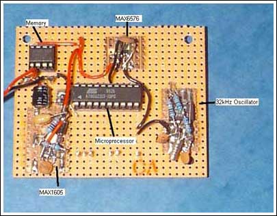
Figure 4. A tight layout of the components that constitute that data-logger board reduces the chances of encountering problems during testing and under actual operating conditions.
Summing the current consumption of each device at 5V, a guess can be made about the worst-case current drain from the battery. The total current consumption of all the devices powered from the 5V rail is
6µA + 750µA + 1.75µA + 250µA + 11µA = 1.02mA.With two cells powering the circuit, an average battery voltage of 2.8V is assumed. To translate the above figure for power consumption into the current that the battery has to source, it must first be multiplied by 5/2.8. Assuming an efficiency of around 80%, the result must be divided by 0.8. The current consumption of the MAX1605 (144µA, powered from the battery voltage) is then added to this figure. Thus the battery can be expected to see a current drain of 2.42mA. Note that this current would be approximately double that number if only one cell is used.
To cross check the above assumptions, the current drain from the battery was measured and found to be 1.88mA, proving that theory was not far removed from practice.
The battery to be used to supply power for a month of logging data could now be determined. A Duracell AA alkaline battery has a capacity of 2.7A-hr. Two cells in series have the same battery capacity as a single cell because the same amount of current flows through both cells. Therefore, with the logging circuit consuming 2.42mA, the maximum time the circuit can log data is
2.7A-hr/(2.42mA × 24hrs) = 46 days.Reducing the number of cells to one would double the current drained from the battery, giving a battery lifetime of only 23 days; two cells are necessary. However, given that the current consumption calculated above is approximate, allowing for a logging time of 46 days should ensure there is enough battery power for the 31 day period - notwithstanding other threats to the circuit like battery self-leakage, the effects of temperature on the battery or the ambient temperature exceeding 85°C by a substantial margin.
When the power supply was connected to the rest of the circuit, the output voltage measured 5.04V across the output tantalum capacitor, with a ripple voltage of 60mVpk-pk. This ripple voltage contrasts sharply with the 400mV ripple voltage measured with an electrolytic capacitor present at the MAX1605 output, indicating the need to use low-ESR capacitors in any dc/dc converter circuit. Since the MAX1605 is bootstrapped (powered from its own output voltage) and the chip is not directly in contact with the input voltage, we can afford to be more lenient on the input capacitor specification; a 33uF electrolytic capacitor was used. In situations where the MAX1605 is connected directly to the input voltage, a tantalum capacitor should be paralleled with a 0.1uF ceramic capacitor and placed close to the Vcc pin.
Incidentally, the MAX1605's bootstrapped mode of operation was chosen because this mode gives slightly higher converter efficiency over the non-bootstrapped mode, due to the increased voltage supplied to the MAX1605's internal FET. Also, once the device has started up, it is powered from its own 5V, allowing the battery voltage to decay to a much lower voltage before the converter stops operating, making the bootstrapped mode ideal for battery operation. The MAX1605 started up at 2.3V (the datasheet specifies a maximum startup voltage of 2.4V), but once operational, the input voltage could be reduced to 1.0V with the converter continuing to operate. This gave further reassurance that the batteries could be significantly discharged without compromising the circuit's operation.
The Software
The code was written as a series of subroutines, which makes it easier to read, write and debug. To conserve power, the processor idles with only its internal timers running, and, as mentioned above, awakens every ten minutes to record the temperature. The processor wakes when interrupted by a timer overflow, which is created by preloading the processor's 16-bit timer with the right number to cause the register to overflow after 10 minutes. Using a 32.768kHz crystal implies a count of 19 million clock cycles every 10 minutes. The 16-bit counter overflows after 65536 counts, so a 1024 prescaler was added. After 10 minutes, with the prescaler added, the timer counts to 19200 ([60 × 10 × 32768]/1024). To ensure the timer overflows after 10 minutes, it is preloaded with (65536 - 19200) = 46336: equivalent to B5hex being loaded into the top 8-bit register.Once inside the interrupt routine, the processor waits for a rising edge on the MAX6576 output and then initiates the 8-bit timer. Since the 8-bit timer can count only to 256, a suitable prescaler for this timer also had to be chosen. The maximum temperature that the logger was expected to see was estimated at 100°C. With the MAX6576 set to give an output of 160us/°K, an output period of 59.68ms would result. This period equates to a count of 1955 clock cycles. Using a prescaler of 8 reduces this count to 244, but at the same time reduces the resolution of the measurement. Running without a prescaler allows the processor to resolve the temperature to 1/5 of a degree (1/[160us × 32768]); with the prescaler, the resolution drops to 8/5°C. The drop in accuracy caused by the prescaler does not significantly affect the accuracy of the circuit though. The 8/5°C resolution can, however, clearly be seen in the temperature plots.
The results were measured and loaded into the E² memory. The I²C routine was written as a series of subroutines handling read as well as write operations for both data and acknowledgements. These subroutines were then incorporated into two other subroutines (Writemem and Readmem) so only these two subroutines had to be called during execution, making the I²C nightmare a trivial exercise. Because the E² memory requires 10ms to program, a delay routine was added to the end of the write cycle.
Finally, a general purpose UART routine was stolen from a previous project; variables within the program were changed as needed.
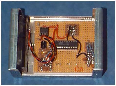
Figure 5. The final assembled unit includes the data-logger board and the battery pack, which appears on the left-hand side of the casing.
Testing
The circuit was assembled and left to log data for 2 days. The logger gained about four seconds per day, which did not exactly meet the 30ppm expected; this is being investigated further.The processor software allowed the E² memory to be written to, or read from, by selection of a port pin (Pin 4). This pin was soldered low during logging and soldered high during read back. The temperature results were not as expected. This problem was discovered to be due to the lack of a 0.1uF bypass capacitor required by the MAX6576. Because of this capacitor, a delay between powering on the temperature sensor and recording its result is necessary. The length of this delay depends on the current limit of the port pin, which, along with the value of the timing capacitor, determines the time to charge the timing capacitor. Once the capacitor was inserted and the delay added, the logger was set logging for another two days. The second download showed a set of results consistent with the author's expectations.
Table 2.
| Count | Temp/°C |
| 192 | 20 |
| 191 | 18 |
| 191 | 18 |
| 191 | 18 |
| 191 | 18 |
Temp °C = [(Count/160us) × (8/32768)] - 273
Table 2. This data represents five successive readings taken by the logging circuit, along with their corresponding temperatures.
Once all the bugs were removed from the circuit, the battery holder was inserted, the circuit was securely mounted and the battery connected. The time was 7:30pm on April 18, 2001. The initial battery voltage was measured at 3.19V.
The circuit was then mounted securely under the hood of the author's car, next to the battery. The car battery is mounted in one of the coolest parts of the engine to prevent the electrolyte from boiling, hence some assurance could be gained that the circuit would not end up a charcoal mess.
Then the waiting began...
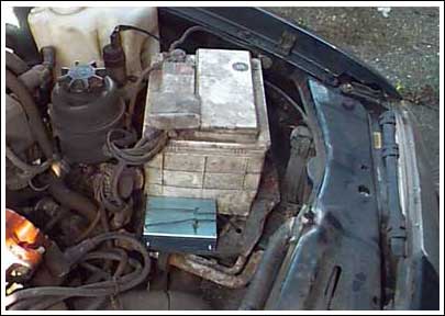
Figure 6. The data logger is located next to the car battery in perhaps the coolest area of the engine compartment. Car designers typically locate the battery in this area to prevent its electrolytes from boiling.
The Results
After 30 days, the data logger was removed and inspected. It (surprisingly) was found to be intact and logging every 10 minutes. The battery voltage had fallen to 2.62V, confirming the original calculations that plenty of life would be left in the circuit. The battery was disconnected and Port B pin 4 was soldered high to prevent memory corruption. The data was downloaded into a PC (the author used a crude Visual Basic routine) and loaded into a file. The data was graphed using Microsoft Excel.The results were as expected, although no extremes of temperature were noted. This could be due to the logger being mounted in a comparatively cool area of the engine compartment as well as the moderate weather in the UK during the latter part of April and the first half of May, 2001. Taking an average of the reading (averaged every 144 results, which is one day) enables us to determine the change in ambient temperature. A marked increase of the measured temperature occurred on day 25. This does, indeed, correspond to a mild heat wave in the south of England during that time.
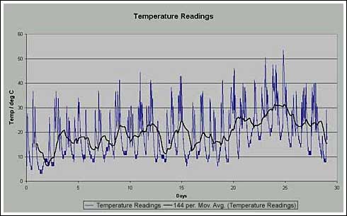
Figure 7. This plot of temperature versus time shows both the individual temperature readings collected and the 1-day moving average of those readings.
Further Developments and Conclusions
No doubt the processor used is not the lowest power device on the market. However, it provided a convenient solution for the task. Should a longer logging period be required, or if a 2-cell alkaline battery stack isn't feasible, there are devices on the market that consume much less power. Keeping the clock frequency as low as possible will also reduce this current.Throughout the logging process, there is no way of determining if the memory has been corrupted. A simple modification of the software can allow the E² memory to be downloaded between successive logs to ensure the data is intact.
The circuit was constructed initially to provide a general-purpose data-logging platform to evaluate various analog and digital sensors. Thus the DC/DC converter was included to provide a constant 5V to all the circuitry. If the sensor does not require 5V, the processor and memory can operate directly from the battery voltage, provided the power-on reset supervisor is changed accordingly.
The circuit worked as expected and surprisingly withstood the vibration of a car owned by an applications engineer. The results showed a good spread of data and it was interesting to note that the extremes of temperature expected (100°C +) were not observed. However, if this experiment is repeated on a summer's day in Egypt, the results may be slightly different.
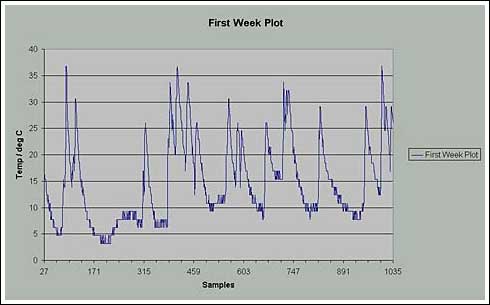
Figure 8. Apparent within this plot of the data acquired during the first week of data logging is the 8/5°C temperature resolution.
A similar version of this article appeared in the June 2002 issue of CIE magazine.