Replacing incandescent bulbs with high-power white LEDs yields higher reliability and greater luminous efficiency. A direct connecTIon between the LED and battery, however, is not ideal. Compared with the alkaline batteries used in most portable applicaTIons, a power source for white LEDs should act more like a current source and offer higher operaTIng voltages. It should also regulate the LED light output to be reasonably independent of the state of the batteries.
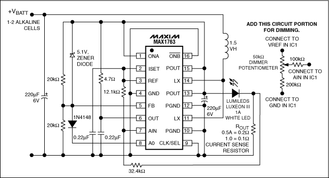
This single-IC driver for white LEDs delivers up to 1A from one or two alkaline cells (Figure 1). A controller for inducTIve step-up converters, the IC includes the necessary power switches. Starting with input voltages as low as 1V, it maintains good efficiency while regulating the LED current. It can operate from 0.8V to 3V while delivering 0.5A, and from 1.5V to 3V while delivering 1A. The circuit also operates well with sources of considerable internal resistance, like batteries at their end of life.

Figure 1. This white-LED driver operates on one or two alkaline cells, with voltages starting as low as 0.8V.
The driver's internal gain block lets you implement a current-regulation loop with few external components: just a current-sense resistor, and an extra resistor to load the internal transconductance amplifier. A 5.1V Zener diode protects the circuitry by setting a voltage-regulation loop and by limiting output voltage when the output circuit opens.
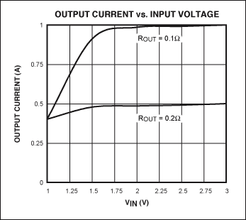
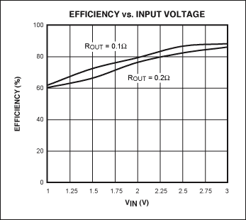
Figure 2 shows the output-current regulation over the operating-voltage range at 0.5A (lower trace) and 1A (upper trace). Figure 3 shows the corresponding efficiencies. Adding the potentiometer circuit shown allows efficient dimming of the light output. Control inputs ONA and ONB can be set for turning the LED on and off with a toggle switch or a momentary-contact pushbutton switch. Figure 1 connects the IC permanently ON. For other ON/OFF configurations, please consult the MAX1763 data sheet.

Figure 2. Output-current regulation vs. operating voltage for the circuit in Figure 1: 1A (top), and 0.5A (bottom).

Figure 3. Operating efficiency at 1A (top) and 0.5A (bottom) for the circuit in Figure 1.
A similar article appeared in the September 19, 2005 Planet Analog Supplement of EE Times.